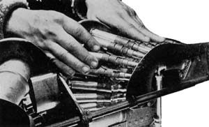
Martin hdraulic upper deck turret

Martin Hydraulic Upper Deck
Martin 250CH-1& 2

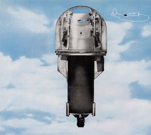
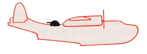
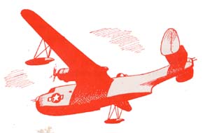
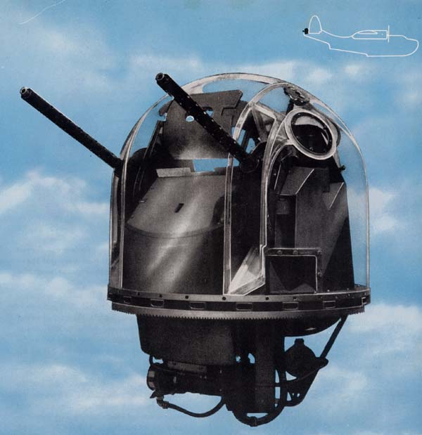
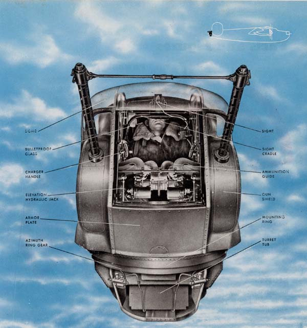
The Martin Hydraulic Upper Deck Turret is the standard Navy installation for many flying boats. It can swing its guns a full 360° and protects the whole upper area of the plane with its deadly efficient cone of fire. There are several models, which for the most part are the same. The Martin 250CH-1 is used in a Martin "Mariner", and the Martin 250CH-3, in the Consolidated "Coronado". The Martin 250CH-2, which is almost identical with the 1 & 3, is the tail turret of the PBM-3D, and will be covered in a supplement to this section.

Restricted

T-83


Facts and Figures

POWER
The Martin 250CH operates hydraulically on pressure built up by a hydraulic pump driven by a constant speed electric motor.

SIGHT
Its sight is a standard Mk 9 sight, fully
described in the introduction to this section.

Elevation limits
Azimuth limits

ELEVATION
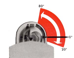
The guns may be raised 80° above the horizontal and depressed 20° below the horizontal.

ARMOR
The armor protection on the front of the turret consists of three sections to shield the gunner from enemy fire in any direction in which he points the guns: 1/2"armor plate on the sight bracket for face protection, 1/2z" armor plate for protection of the body, and 3/8" armor plate for protection of the ammunition magazines.


AZIMUTH
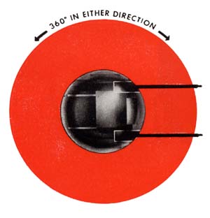
The turret can move 360°—a full circle—in azimuth.
STOWING POSITION
The stowing position is 0° elevation and 180° azimuth, guns pointing straight aft.
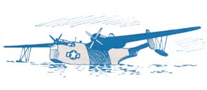
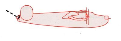
PBM silouette

Restricted

T-84


Getting In

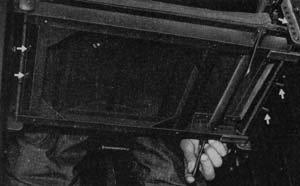
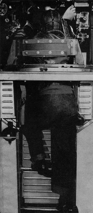
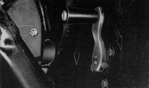
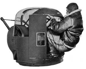
The Martin Hydraulic Upper Deck Turret is one of the easiest to enter. First of all, before you get in make sure that the deck turret switch has been turned to the on position on the flight engineer's panel. Just outside the turret on a junction box, conveniently located on a bulkhead, is a switch and a red indicator light, which provides for turning "on" or "off" the power to the turret. In the turret is a similar switch marked main power with a red indicator light directly below it. In turning on the power it is best to wait until you are in the turret, as the switch on the outside junction box is to be used for emergency purposes only. Now enter the turret headfirst from the rear of the ammunition box by climbing up the two steps, using a convenient portion of the structure of the turret as a hand grip to help you. While standing on the top of the ammunition box covers, reach down and pull the seat up until it locks over the right hand seat support bar. Then look through the sight to see if you are at the proper height. If you are not, get out of the turret and adjust the seat. This is accomplished by pinching together the pins in the seat support bars, which are located on each side of the seat, and raising them to the next holes above or below. On completion of this, climb back into the turret. Fasten the safety belt and you are now ready to operate.
Pulling the seat up

Getting into the turret

Restricted

T-85


OPERATING THE TURRET

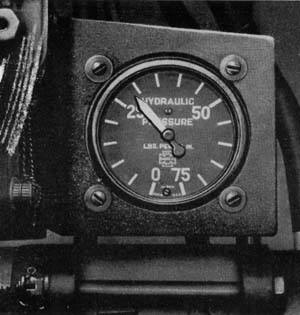
Low pressure gage

. . Where to Find the Controls
. . How to Use Them

Putting the Martin 250CH Turret into operation is a relatively simple job.
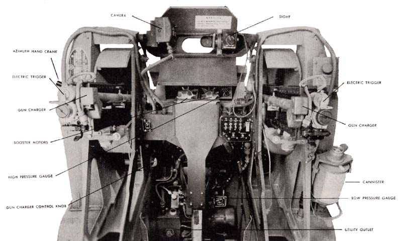
First of all, look down over your right foot and you will see a low-pressure gauge which should read 25 lbs. to 30 lbs. pressure. It is very important that this pressure be present as it insures smooth operation of the turret. Directly in front of you on the right side is the control panel. On it you will see a switch marked main power (A) with a red indicator light (B) below it. Flick this switch to the on position and the red light will light up on the control panel and on the junction box just outside of turret, indicating the power is on.

Control panel

Restricted

T-86


On the left side of the control panel you see another switch all by itself, marked pump motor switch (C). Raise this to the on position. Lift the little red plastic cover on the right side of the control panel and flick the gun-end-sight switch (D) to the on position. The control handles are located below and back of the breast plate in which the control panel is mounted.
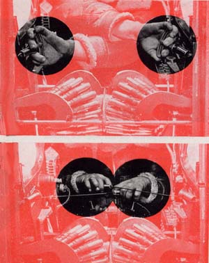
To start the pump motor use the bottom edges of your hands to press down the two safety switches. When the motor is running, the handles will automatically go to neutral position. For this reason it is best to press the safety switches down before grasping the hand grips of the control handles. If this is done, the control handles will move to the neutral position without moving the turret. If the control handles are in any other position than neutral and the safety switches are closed, the turret will start, causing immediate and violent action. Either safety switch will operate the turret.
Depressing the safety switches also turns on the sight and provides power to the booster motors so that they will operate when the guns are fired.
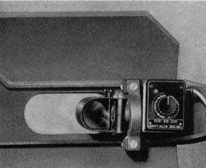
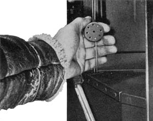
To adjust the brightness of the sight to light conditions use one hand to hold the control handles, keeping the safety switch depressed, and turn the rheostat on the sight.
To operate the turret turn the control handles in the direction you desire the turret to move. For azimuth (right or left) the control handles are operated exactly like those of a bicycle. For elevating the guns move the upper part of the control grips backward; and for depressing the guns, move the top portion of the control handles forward. Don't jerk the controls—move them smoothly and deliberately.

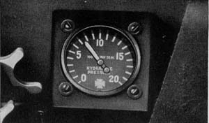
High pressure gauge
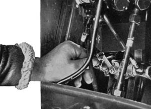
Above the control panel, and right center, is the high pressure gauge. As soon as the pump is operating, check to see if it reads the desired 750 lbs. pressure. While operating the turret, from time to time check this gauge to see that the proper pressure is maintained. Right under your index finger on both control handles are the triggers. Either trigger will fire both guns.
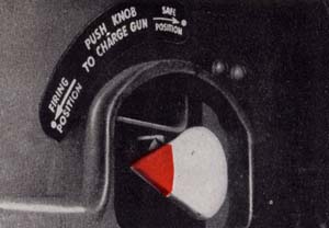
Gun charger control knob
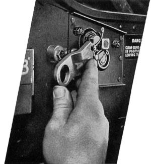
Next to your left knee is the hydraulic gun charger control knob, which operates the gun chargers located on the inboard side of each gun. To charge the guns turn the control knob to the Firing position. Depress the control knob sharply. Both guns will be charged at once and ready to fire. If the control knob is turned to Safe before depressing, the gun bolts will remain in the retracted position, which provides access TO remove a jam.
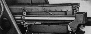
Gun chargers

Restricted

T-87


Turret layout
Using Auxiliary Equipment

The oxygen system The turret oxygen system is connected to that of the airplane through a swivel joint in the base of the turret. The system consists of a rebreather unit, a cannister, and a nose piece. The rebreather is mounted on the right side of the magazine under the expended ammunition container. The cannister is located on the outboard side of the right ejection chute casting and is connected by a flexible hose to the oxygen mask. However, you will find in many of the existing PBM and PB2Y airplanes that the oxygen system has been done

Regulator valve

away with, because it is not necessary for these airplanes to fly at high altitudes while on patrol. The cord to the heating suit is plugged into an outlet on the junction box, which is located directly above your left foot. This is turned on at the control panel by the utility switch (E). The interphone jack box is attached to the right ejection chute casting. This is where you plug in your jacks for your headphones and throat microphone. On the front of the box is the "push-to-talk" button that operates the interphone system when you wish to speak. Two trouble lights of the spotlight type are mounted on ribs from the top of the dome, one on either side of the escape hatch. A ball swivel joint on each light enables you to direct the light in any direction desired. The dome light switch (F) is located on the control panel.

Restricted

T-88


Provisions have been made for installation of a gun camera on the left side of the sight. To put the camera into operation it is necessary to have the camera switch (G) and the main power switch "on", and the trigger and safety switch depressed.
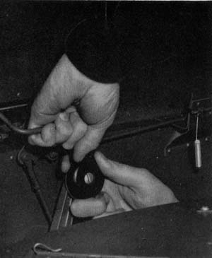
In the event that the power fails, a manual azimuth drive is provided so that you may rotate the turret. The drive crank is stowed on a spring clip mounted on the aft face of the left ejection chute casting. Remove the crank from the clip and insert it in the hole on the right inboard side next to your right knee. This ties the crank directly into the azimuth gear mechanism. Turning the crank one way or the other moves the turret in azimuth. You will find the crank extremely helpful in testing the fire interrupter and boresighting the guns when a slow, carefully controlled amount of azimuth movement is necessary.
Azimuth manual hand crank

Before going back to power operation be sure to remove this azimuth manual crank. If you have it engaged it will whirl around and may break your hand or leg.

No manual elevation mechanism is provided in this turret. However, in models which are about to be produced, manual operation will be provided for both elevation and azimuth.

Getting Out
Getting out of the turret you will find just as simple as getting in. First of all, move the guns to the stowing position—guns at zero elevation and 180° azimuth, pointing straight aft. Turn off all switches. Disconnect all auxiliary units you have been using.
Brace yourself against the back of the seat and reach down on your right side and depress the seat release. The seat will then swing down out of the way. All you have to do now is to climb down two steps and you are out of the turret.

Emergency Exit
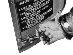
If it is necessary for you to get out of the turret in a hurry, an emergency exit is possible through an escape hatch in the plastic dome. Two plastic handles are located on either side of the hatch and by turning them a quarter of a turn, the hatch will fall inboard. By standing ,on the seat you will find it an easy job to crawl out of the top of the turret. Getting out of the turret

Getting Out Operating hand crank

Restricted

T-89


Preparing the Turret for Combat
You have now read how to get into the turret, how to operate the controls and auxiliary units, and how to get back out. With this information you should have no trouble in taking over the turret and operating it in combat.
To be a specialist in the Martin 250CH you will need additional instruction on how to get the sight and guns ready for a mission, harmonize them, and load ammunition. You will find this information in the following pages.

The Sight
The Navy Mk 9 sight fits into the gun sight bracket directly behind a 1/2" armor plate which protects your face. To adjust the sight, as it may be sometimes necessary in harmonizing it with the guns, make the adjustments on the sight head. For full instructions see the section on the Mk 9 sight in the general introduction.
MK 9 sight
Adjusting the Guns
Ammunition feeds
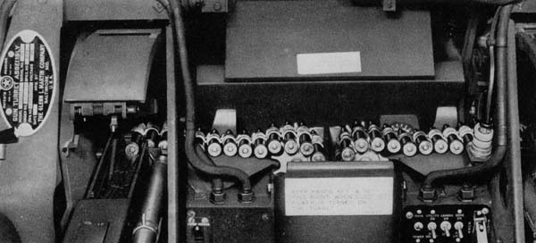
The guns are mounted in the Martin Ball to feed from the inside-the right gun feeds from the left and the left gun feeds from the right. Each gun is installed with an Edgewater E-10 adapter and is bolted to the front and rear mounts in the gun cradles.

Restricted

T-90


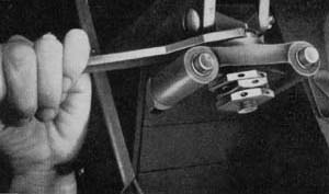
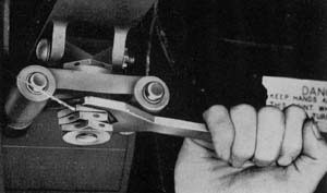
The guns may be adjusted up, down, or sideways in their cradles by means of an adjustment nut assembly which is locked into place by jam nuts. An elevation adjustment nut controls the up and down movement. An eccentric nut controls the sideways motion.
Elevation adjustment nutEcentric adjustment nut
Harmonizing the Guns and Sight

There are a number of ways to harmonize the guns and sight in the Martin Hydraulic Deck Turret. The exact procedure will be defined by the Squadron Gunnery Officer. A handy method is to line up the sight and boresight the guns on some small object, such as a tree or chimney, at least 1000 yards from your plane. To do that remove the back plates and bolts from both guns, or use a boresight tool so that you can look through the gun barrels without removing the parts. Turn the turret until the guns point at the object you have selected.
Now line up the sight, using the azimuth hand crank to move the turret until the dot of the sight is squarely on the object. Don't move the turret again. Now boresight through each gun barrel to line up each gun. Adjust each gun by its rear mount adjustment nuts until the spot the sight is centered on is exactly in the center of each gun bore. Sometimes the amount of adjustment in the rear mounts of the guns may not be enough. In that case, boresight each gun on the small object selected. Then you must make adjustments on the sight head to line up the dot on the same object.


Boreshight templete

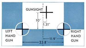
Another method of harmonization is to line up the sight and guns on a special pattern stand, or template, such as the one illustrated here. Set up the stand as level as possible at least 50 yards from the side of the plane. Center the guns in their mounts. Then boresight each gun on the pattern stand and center the sight on the sight cross, using the standard technique described in the Sights and Sighting section of this manual. Both methods described here are parallel harmonization.

Restricted

T-91


Loading Ammunition

Flaking the ammunition belts

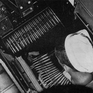
The Martin Hydraulic Upper Deck carries its ammunition in two built-in magazines, separated by a steel partition and mounted under the feet of the gunner. These double magazines are loaded through sliding removable doors on top and hold 600 rounds of .50 cal. ammunition for each gun. The top of the ammunition box and the removable doors also serve as a footrest for the gunner. To load the magazines:

1.
Remove the foot plates at the top of the ammunition box. This is done by pulling the spring-like pin under the footrest panels and then skidding the foot plates aft and off.
2. Remove the forward and aft pins of the feed chute. Remove the chute.
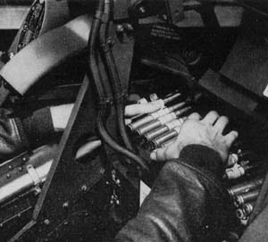
3. Load the ammunition belts by flaking them back and forth across the magazine.
Pullling ammunition into guns4. When ammunition boxes are full reinstall the feed chute and its pins.
5. Lower a wire hook or an ammunition thread sling down the top of the booster feed and through the feed chute attaching it to the ammunition belt in the magazine.
6.. Reinstall foot plates at the top of ammunition box.
7. Pull each ammunition belt up through the chutes until one or two rounds of ammunition are engaged in the booster sprockets.
8.. Lift the cradle cover and gun cover. Pull enough ammunition to be loaded into the guns.
9. Close the gun covers and cradles.

Restricted

T-92


Removal of Empty Cartridge Cases and Links

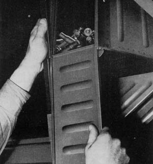
On either side of the seat, attached under the azimuth track, are the expended ammunition containers—one for each gun. To remove the empty links and cartridge cases, slide down the access doors on the back of each container after pushing in the latching catches on the access doors. Clean out the empty cartridge cases and links. Replace the access doors.

Opening access door to expanded ammuniction container

Pre-Flight Routine

. . . FOLLOW STEP BY STEP

1. Install the barrels and oil buffer groups in the guns—leaving out the bolts and back plates.
2. Check harmonization of the guns and sight by boresighting on pattern stand or some other object 1000 or more yards away.
3. Make sure the bolts are assembled properly to feed from the right for the left gun and from the left for the right gun. Install bolts and replace back plates on both guns.
4. Try to rock the guns in their mounts to make sure they are securely mounted. Check to see if the adjustment and jam nuts are properly safetied.
5. Check filler valve. It should be in the "RUN" position and safety wired.
6. With the pump in operation, operate the gun charger valve knob in both "SAFE" and "FIRE" positions.
7. Inspect the hydraulic system and lines carefully. This should be done with and without the pump operating. If there are any leaks, report them immediately.

8. Inspect electrical leads and flexible conduits (Breezes) to determine if they are frayed or damaged.
9. Check all Cannon plugs to see that they are properly seated and screwed up tight.
10. Check oxygen connections to be sure they are tight.
11. Make sure plexiglas dome and escape hatch are properly secured and clean.
12. Check low pressure gauge to see if you have 25 to 30 Ibs. pressure required.
13. Operate the turret to determine if the high pressure gauge reads required 750 lbs.
14. Check ease of operation in elevation and azimuth. Stop turret with pump running (control handles in neutral). Check for "creep."

PBM in flight

Restricted

T-93


15. Check for "line knock" (air in hydraulic system) while operating turret in all extremes. If any is noticeable, report it to maintenance man.
16. Operate the turret in elevation to determine if the limit stops are functioning properly.
17. With the guns completely depressed, carefully rotate the turret to determine if the structural interrupter keeps the guns from swinging into the fuselage.
18. Insert a test light in place of electric trigger control, and with triggers depressed, rotate the turret across the portions of the plane into which the guns could fire. The test light will go out in this area. With a boresighting tool, check the distance from the surface the interrupter cuts out.
19. Turn on the sight and gun switch, depress the safety switch, and rotate the sight rheostat from dim to bright to adjust the brightness of the reticle to existing light conditions. Make sure the reflector plate of the sight is clean.

20. Plug in your headphones and microphones to test if your crew mates can hear you and you can hear them.
21. Plug in your heating suit and make sure it begins to heat.
22. Make sure both trouble lights are operating.
23. Inspect all ammunition belts to determine that the rounds are in good condition and properly belted.
24. Check booster motors by tipping them toward the guns. Make sure they cut on and off sharply without lagging.
25. Load ammunition magazines. Feed the double link up over the booster motors' sprockets, and press the first round into the feedway of each gun. You will not charge your gun until you are in the air and so ordered by your plane captain.


PBM rear quarter

Before Landing
1.
Run the turret to its stowed position—0° elevation and 180° azimuth, guns pointing straight back.
2. Clear the guns by lifting the gun covers, removing ammunition and charging them twice.
3. Remove all ammunition from feedway; check all switches and make sure they are off.
4. Disconnect any auxiliary equipment that you have been using.
5. Get out of the turret.

After Landing
1. Remove all ammunition from chutes and magazines.
2. Open access doors on the expended ammunition containers on either side of the turret and clean out empty cartridge cases and links. Replace the access door on completing the job. 3. Field-strip the guns by removing their working parts. Clean and inspect gun receivers, then detail-strip the parts you have removed from the gun, cleaning them and making a thorough check of their condition. Do not leave excess oil or cleaning fluid in turret.
4. Report any malfunction of turret or guns noted on the mission. PBM on the water

Restricted

T-94


Martin hydraulic tail turret

The Martin Hydraulic Tail Turret
Martin 250CH-2

There is little difference between the Martin 250CH-1 and 250CH-3 Deck Turrets and the Martin 250CH-2 Turret used in the tail position of the PBM-3D airplane. Both types are operated exactly the same. The information on the following page will outline the major differences between the two types.

Restricted

T-95


Facts and Figures

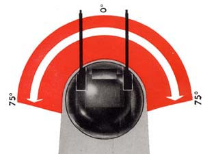
AZIMUTH
The Martin 250CH-2, being a tail turret, is provided with an azimuth movement of 75° on either side of the center line of the ship.

Azimuth limits

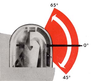
ELEVATION
In elevation it can raise its guns 65° above horizontal and depress them 45° below horizontal.

Elevation limits

MARTIN TAIL TURRET
As the Martin 250CH-2 is a tail turret, never remain in it during takeoffs and landings. Your additional weight in the tail would put undue stress on the plane besides making it unbalanced.
To enter the turret crawl in on your hands and knees. When you are inside, straighten up, and pull the seat up until it locks over the right

Foot brackets

hand seat support bar. Look through the sight to see if you are at the proper height. If not, adjust the seat as you would in the Martin 250CH-1 or 3 Deck turret. In this turret you do not place your feet on the top of the magazines as you would in the deck turret, but on foot brackets.

Keep your feet on the foot brackets at all times while operating the turret or it is possible that you may get them jammed between the turret and the structure of the ship.

at all times while operating the turret or it is possible that you may get them jammed between the turret and the structure of the ship.
To get out of the turret first run it to its stowing position — 0° elevation and 180° azimuth — guns pointing straight aft. Then crawl out of the turret in a manner similar to that used in entering. No magazines are provided in the turret, but they are located in the hull of the airplane, one on either side. Each of these magazines holds 1000 rounds. The ammunition travels along both sides of the hull on roller tracks and enters the turret between the gunner's feet. The empty cartridge cases and links are carried overboard through chutes. The check off routine for PRE-FLIGHT on both Martin Deck and Tail Turrets for the most part is the same with the following substitutions:
Preflight
16. Operate the turret in both extremes of elevation and azimuth to check the limit stops.
17. Disregard this check, as no structural interrupter is provided in the tail turret.
18. Disregard this check, as no fire interrupter is provided in the tail turret.

BEFORE-LANDING and AFTER-LANDING procedures are exactly the same.

Restricted

T-96


Consolidated tail turret

The Consolidated Tail Turret
Consair 250CH-3 or M.P.C. 250CH-6

The Consolidated tail turret is a double stinger in the tail of the PB2Y-3 Coronado and the
PB4Y Liberator. In some Liberators ii is also used as a bow turret. It is a versatile gun mount
providing a large cone of fire.
There are two models—the original Consair 250CH-3 and the new MPC 250CH-6, which is
now in general use and has some marked mechanical improvements.
In operation the two models are basically the same.

Restricted

T-97


Facts and Figures

POWER
The Consolidated Tail operates hydraulically, on pressure built up by a hydraulic pump driven by a constant speed electric motor.

SIGHT
Its sight is a standard Mk 9 sight, fully
described in the Sights and Sighting section of this manual..

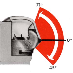
Elevation limits
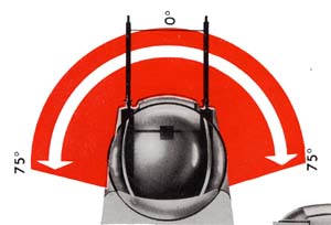
Azimuth limits

ELEVATION
In elevation, the turret guns can be lowered and raised from 45 degrees below the horizontal level to 71 degrees above horizontal.

ARMOR
A bulletproof glass panel, 21/8 inches thick, protects the gunner in front. Directly below it is a 7/8 inch armor plate panel, and to the right and left of the gunner's knees are two more small panels, 3/8 inch thick.


AZIMUTH
The turret moves in azimuth about 75 degrees to either side of the ship's centerline — from almost straight out to the left to almost straight out to the right.
STOWING POSITION
The stowing position for turret and guns is 180 degrees in azimuth and 60 degrees in elevation—guns pointed back from the tail and two-thirds of the way between level and straight up.
PB4Y silouette

Restricted

T-98


Getting In

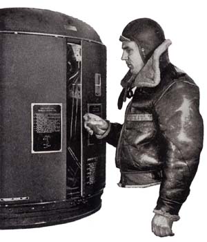
When you step into the Consolidated Tail for the first time, approach it with care. Unless the turret is properly locked, it may swivel and trap a man trying to go through the doorway. The method of getting in illustrated on this page is the only safe way—follow it step by step.
And remember, as you get into the turret for your first look around, that ordinarily you would enter only after the bomber is in full flight, and would get out before the landing. Quick changes of speed during takeoffs and landings make any tail turret an extremely dangerous place to be at those times.


1.
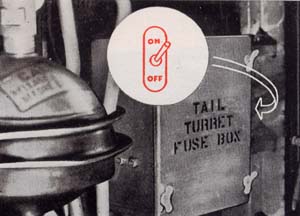
Turn on the main power switch just outside the turret on the fuselage of the plane.

Main power switch
OPening the turret doors2.
Opening the turret doors

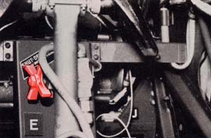
Reach into the turret and make sure that the main shut off valve, a red spindle knob to the left center, is closed. The valve should be turned all the way in. If it is open, a mere touch on the control handles might set the turret moving and trap you in the doorway. Always make sure the main shutoff valve is closed before entering or leaving the turret.

Main shutoff valve

Restricted

T-99


Azimuth emergency release valve


4.
Make sure the azimuth emergency release valve under the seat is closed.
5.
Make sure the elevation bypass valve, a
small handle below and to the left of the control unit, is closed. The handle should be up

Grasping the handles above the doorway6.
Grasp the two handles just above the doorway, and, chinning yourself, swing both feet straight into the turret pit. Then get into the seat.
7.
Pull down on the door cable, by grasping the red knob on your right, to close and lock the doors behind you. Be sure the doors are tightly latched.


Pulling the red knob

Restricted

T-100


Elevation mechanism lockAzimuth mechanism lock

8. Remove the azimuth mechanism lock on your right and the elevation mechanism lock on your left. Put the locks in their clips on the turret wall.


OPERATING THE TURRET

. . . where to find the controls
. . . how to use them               

Close at hand, as you sit in the Consolidated Tail, are all the switches, valves, and controls. They are easy to get at and easy to use. But be sure to turn on the switches and open the valves in the order shown here.

1. Open the main shutoff valve.

Main shutoff valve

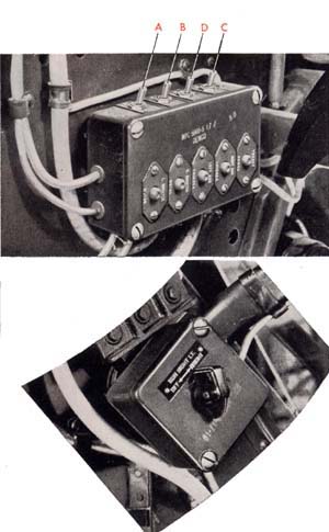
2. Turn on the power switch (A) on the junction
box beside your left knee.
3. On this same panel flip on the booster motor
switch
(B) and the trigger switch (C). If you
are using a gun camera, flip on the gun
camera switch
(D).
4. Turn on the sight rheostat, near your left
shoulder, and rotate it to adjust the brightness
of the light in your sight.

Power switches and sight rheostat

Restricted

T-101


Control handles
5.
Grasp the control handles directly in front of you, and you are all set to go. To move the turret, turn the handles just as you would steer a bicycle—to the right to go right, left to go left. Press down on the heels of the handles to raise the guns. Pull up on them to lower the guns. The other controls you will use in combat are close at hand.
The triggers (A) are on the control handles, right under your index fingers. The push-to-talk button (B) that opens the interphone system for you to speak is on the right handle, under your thumb. A set of reset buttons (C) protecting the main electrical circuits is mounted on the side of the junction box—each button labeled with the name of the circuit.
6.
The charging handles are on either side of the bulletproof glass in front of you. To charge the guns, reach forward and grasp the handles cross-arm, holding the left handle with your right hand and the right handle with your left hand. Pull back on them sharply as far as they will go. Don't ride the cables on the return action. Still holding the handles, allow them to snap back on their own power.


Charging handles

Restricted

T-102


Using the Auxiliary Units

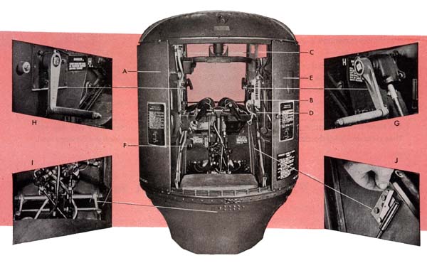
You will find a demand type oxygen regulator (A), with hose connection for your mask, near your left shoulder. The oxygen supply is drawn from the ship's central tanks.
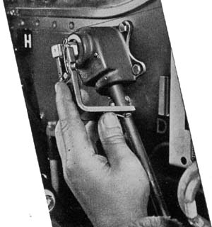
The heated suit plug-in (B) is mounted on the right wall of the turret enclosure near your right shoulder. The interphone jack box (C) is on the right wall of the turret, too, near your cheek; from it lead the interphone jacks (D). A trouble light and switch (E) fit in a holder in the upper right-hand corner of the turret enclosure. A warning bell (F) on the left forward wall of the turret is connected with the pilot's compartment—he will ring it when he wants to land, notifying you to get out of the turret. Shafts for manual operation of the turret in emergencies are on the right and left side of the turret seat—the right shaft (G) for azimuth movement, the left (H) for elevation. The two hand cranks are stored in clips on either side. At your feet are two foot-firing pedals (I), with a foot-firing mechanism lock (J), which allow you to fire the guns in manual operation.

To change to manual operation:

1. Close the main shutoff valve. Open the bypass and emergency release valves.
2. Slip the hand cranks on the manual shafts.
3. Pull the foot-firing mechanism lock up into its OPEN position.

Always push the foot-firing mechanism lock DOWN into its locked position after manual operation. Never charge the guns unless this lock is down.

Restricted

T-103


Getting Out
When you get out of the turret—before the landing if you are on a flight—be as careful as you were when you got in. Remember that the doors can trap a careless gunner on the way out as well as on the way in.
First move the turret to stowing position—guns pointed back and to 60 degrees elevation. Then turn off the sight, trigger, booster motor, and mam power switches on the junction box. Close the main shutoff valve, and replace the azimuth and elevation mechanism locks which you removed when you got in.
The turret is now locked in place. Open the doors by pulling the cable on your right and step out. Then close and latch the doors behind you and turn off the main power switch on the fuselage wall.
Pulling the cable
Preparing the Turret For Combat
With the practical data in the preceding pages, you could take over the Consolidated in combat. However, that will be only part of your job. The rest of your job—harmonizing the sight and guns, and loading ammunition ready for a mission—is explained in the following pages.
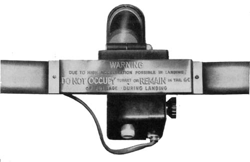
MK 9 sight with warning bracket\

Adjusting the Sight
The Navy MK 9 reflector sight fits into a bracket mounted on top of the sight cradle directly in front of you. To adjust the sight as it may be sometimes necessary in harmonizing it with the guns, make the adjustments on the sight head. For full instructions in making these adjustments, see the section on the MK 9 sight in the general introduction.

Restricted

T-104


Adjusting the Guns

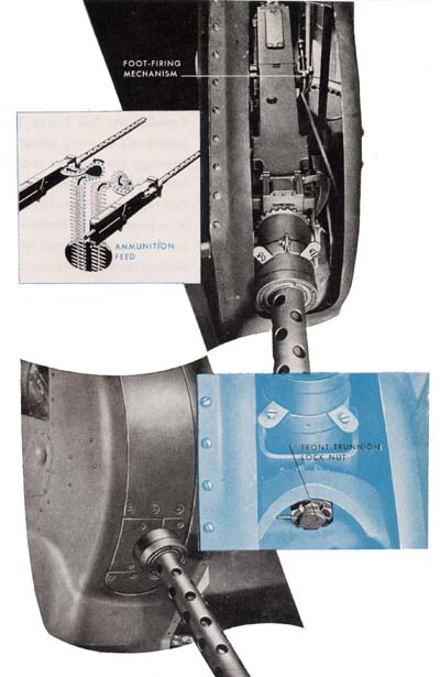
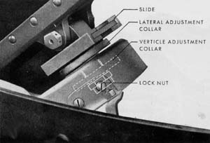
The guns are mounted in the Consolidated Tail to feed from the inside—the right gun from the left, the left gun from the right. Each gun is held in its cradle by a rear trunnion block and slide and a front trunnion stud bolted into a mounting hole in the cradle. The rear trunnion block, attached to the gun, dovetails into the slide mounted on the cradle; check to make sure the block fits. The front trunnion stud is held by a lock nut and cotter pin. Special charging units are installed on the inside plates of the guns' receivers, and link ejection chutes on the outside. Make sure that the bolts mounting the charging units are safety wired, and that the cable connections have cotter pins. Special foot-firing mechanisms are mounted on the outside of the guns and connected to two foot-firing pedals. The pedals operate plungers which trip the sears in the guns. When you assemble the bolts for the guns, make sure the square ends of the sear slides are on the outside of each gun. Mounting bolts on the foot-firing mechanisms must be safety wired. The guns are adjusted up, down, or sideways in their cradles by rear mount adjustment collar and lock nut assemblies.

Gun adjustments

Adjusting collar and nut assembly

To make adjustments on either gun:
1.
Loosen the front and rear trunnion lock nuts.
2. Turn the top lateral adjustment collar right or left to move the rear of the gun from side to side.
3. Turn the bottom vertical adjustment collar right or left to move the rear of the gun up or down.
4. Tighten the lock nuts. By means of these adjustments the guns can be centered in their mounts. Simply turn the collars to the approximate centers of their lateral and vertical adjustment movements. A little practice will enable you to do this quickly and accurately.

Restricted

T-105


Harmonizing the Guns and Sight

There are a number of ways to harmonize the guns and sight in the Consolidated Tail Turret. The exact procedure will be defined by the Squadron's Gunnery officer. A handy method is to line up the sight and boresight the guns on some small object such as a tree or chimney at least 1,000 yards from your plane.
First remove the two access plates from the rear of the turret. Simply press in to release them. Remove the backplates and bolts from both guns or use a boresighting tool so that you can look through the gun barrels without removing the parts. Then center the guns in their mounts. Now line up the sight using the hand cranks to move the turret until the dot of the sight is squarely on the object. Lock the turret in this position with the mechanism locks.
Then boresight through each gun barrel to line up each gun. Adjust each gun by its rear mount adjustment collars until the spot the sight is centered on is exactly in the center of each gun bore. Sometimes the amount of adjustment in the rear mount of the guns may not be enough. In that case, boresight each gun on the small object selected, then you must make adjustments on the sight head to line up the dot on the same object.

Another method
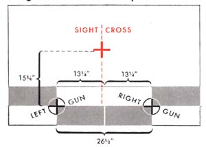
of harmonization is to line up the sight and guns on a special pattern stand, or template, such as the one illustrated here. Set up the stand as level as possible at least 50 yards from the side of the plane. Center the guns in their mounts. Then boresight each gun on the pattern stand and center the sight on the sight cross, using the standard technique described in the Sights and Sighting section of this manual. Both methods described here are parallel harmonization.

Boreshight templete
Illustration of gun harmonizing


Loading Ammunition

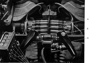
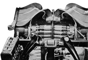
The ammunition cans, one for each gun, hold about 400 rounds each. They are outside the turret in the fuselage of the plane, and the ammunition belts feed through flexible guides up through the floor of the turret to the guns. To load the guns, first pull the ammunition belts up through the floor of the turret, double-link end up. Drape them forward over the booster motor cylinders and sprocket wheels, makingAmmunition belts draped over booster motors


Restricted

T-106


sure the rounds rest evenly in the sprockets. Then twist the belts slightly and curve them up over the feed chutes to the guns' feedways. Just before the takeoff, press the first links of each belt into its feedway, and the guns are ready to be charged and fired.
Pressing links into feedway

Preflight Routine

. . . FOLLOW STEP BY STEP

1. Install the guns' barrel and oil buffer groups in the guns—leaving out the bolts and back-plates.
2. Check harmonization of the guns by boresighting the guns on some small object 1,000 yards away, or on a pattern stand.
3. While harmonizing the guns, make sure the manual system of operation is working properly.
4. Make sure the gun bolts are assembled properly, to feed from the right in the left gun and from the left in the right gun. Also make sure that the square ends of the sear slides face the outside of the guns. Then install the bolts and backplates in both guns. Replace the gun access plates.
5. Try to rock the guns in their cradles to make sure they are securely mounted. Check to make sure that the front and rear trunnion mounting studs and bolts are safety wired.
6. Check the hand charging units on the inside of the guns and the foot-firing mechanisms on the outside of the guns to make sure they are securely attached and their mounting bolts safety wired. The cable connections to the charging units must have cotter pins.
7. Inspect the hydraulic system and lines. If there are any excessive leaks, report them.
8. Inspect the electric cables. Make sure all cannon plug connections are tight. Report any frayed or damaged cables.
9. Check the oxygen connections.

10. Make sure the Plexiglas dome and bulletproof glass are clean.
11. Check the hydraulic fluid level gage on the reservoir in the actuator unit mounted on the fuselage wall. If the oil is below the FULL line, notify turret maintenance.
12.. Turn on the main power switch on the fuselage wall. Listen for the hum of the electric motor in the actuator unit, and watch the pressure switch in the unit to see that it is working properly.
13. Open the turret doors. Look in and make sure the main shutoff valve, azimuth emergency release valve, and elevation bypass valve are closed. Then get in the turret.
14. Turn on the sight switch and rotate the sight rheostat from dim to bright to adjust the brightness of the light and make sure the rheostat is working properly. Flip the sight filament switch to both positions. If either filament is burned out, replace the bulb. Make sure the optic head is clean.
15. Turn on your trigger switch. Check head-space in the guns. Then pull one trigger at a time, charging the guns each time, and check electric triggers for proper adjustment—listen for a "click" as the firing pins of the guns release. Both guns should fire from either trigger.
16. Turn on the booster motor switch. Test the

Restricted

T-107


booster motors by tilting the boosters toward the guns. Make sure the motors cut on and off sharply, without lag.
17. Turn off the trigger switch and test the foot-firing system by opening the foot-firing mechanism lock and stepping on the foot-firing pedals. Listen for a click as the plungers operate the guns' sear slides.
18. Remove the azimuth and elevation mechanism locks from the shafts and place in their clips. Make sure these locks are removed before trying to run the turret.
19. Open the main shutoff valve, turn on the power switch, and run the turret under power in azimuth and elevation, to check on ease of operation. Make sure the turret operates with either safety switch held down. Run the turret as far to the left and right as it will go to make sure the limit stops halt the guns before striking the plane. Stop the turret and check for creep.
20. Put on your oxygen mask, connect it, and test by turning on the direct flow valve. Check the gage to make sure there is proper pressure, in the tanks, as determined by your crew chief. Close valve.
21. Plug in your headphones and microphone

to test whether your crew mates can hear you and you can hear them.
22. Plug in and test your heated suit and the rheostat.
23. Make sure your trouble light operates. Pull the light out on its cord to make sure the retractable reel is working properly.
24. Check operation of the warning bell by having the pilot ring it from his position.
25. Close all valves, turn off all switches, and get out of the turret.
26. Inspect the ammunition belts to make sure the rounds are in good condition and properly belted.
27. Load both ammunition cans. Feed the belt through the flexible guides; pull them up through the chutes in the turret, over the booster sprockets, and press the first rounds into the guns' feedways.
28. Make a last visual check of the turret.
29. Move the turret by hand crank into stowing position—guns pointing straight back and raised two-thirds of the way between level and straight up. Replace the azimuth and elevation mechanism locks on their shafts in locked position, get out and close the turret doors —ready for the takeoff.

Post-Flight

Before Landing
1. Clear guns by opening the gun covers and hand charging the guns twice. Remove ammunition from feedways and upper chutes.
2. Run the turret to stowing position.
3. Close the main shutoff valve and turn off the switches. Replace both mechanism locks.
4. Get out of the turret and fasten the doors.
5. Turn off the main power switch.
After Landing
1. Remove all ammunition from the flexible

guides and ammunition cans.
2. Remove gun access plates and field strip guns.
3. Clean the gun casing groups, inspecting their condition as outlined in post-flight checks in the Guns section of this manual.
4. Then detail strip the parts removed from the guns, cleaning and inspecting them as outlined in the Guns section.
5. Report any malfunctions of turret or guns noted on the mission.

Restricted

T-108


Previous Section - Table of Contents - Next Section

Transcribed and formatted by Thomas Wildenberg for the HyperWar Foundation