
CHAPTER 2.
ERRORS AND CORRECTORS.
1. The purpose of this chapter is to explain the fire control and ballistic errors
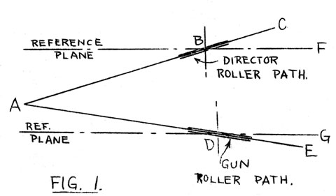
for which correctors are provided in the various fire control installations, and the
usual methods of correction.
Inclination of Roller Paths.
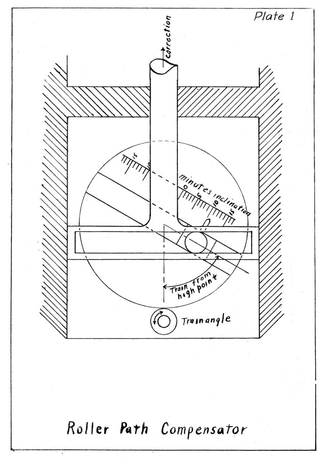
2. When roller paths for, guns and gun directors are installed
while
the ship is being built, every effort is made to cause them
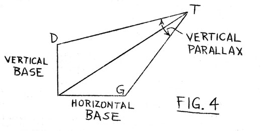
all to be parallel to one another. However, it is practically
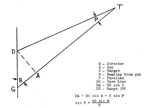
impossible
for this to be accomplished with the precision required
by present day fire control installations. Settling of the ship's
structure
and even variations in speed and loading may cause
additional
errors in parallelism.
3. Referring
to Fig. 1, assume that the director roller path
has a
high point at relative bearing 90°; that the gun roller
path has
a low point at 90°; that the sights of the gun and
director
when trained dead ahead were brought parallel to the
reference
plane; that the sights were unchanged,- and the gun and
director
held fast in elevation but trained from dead ahead to
90°
relative. The director line of
sight is now along BC and
--10--
makes an angle CBF with the reference plane (BF) The gun line of sight is along DE:
and makes an angle GDE with the reference plane. The two lines of sight,
which were parallel when trained dead ahead, now make
an angle BAD (= CBF + GDE) with each other. For parallelism with the director
line of sight, the gun must be elevated through the angle BAD.
4. Actually the inclinations vary both in amount and in direction. In lining up the
battery, one director roller path (usually
that of
the conning tower director due to its steady foundation
is
selected as the reference plane and the inclinations of
the
remaining director and gun roller paths of the battery are
obtained with respect to this director's roller path.
5. The roller path correction varies with the angle of train,
its
value being the product of the inclination at the high point
and the
cosine of the angle of train from that point. The sign
of the correction is such as to depress the gun at the high
point.
6. Corrections for roller path inclination are applied
mechanically
at each gun mount, the mechanism (see plate 1)
consisting
essentially of a crank or eccentric of length equivalent to the maximum inclination,
the position of which is controlled by
the
angle of train. The resulting correction is applied to the
gun elevation input to the elevation indicator (or elevation repeat
back). In effect this makes the input equal to the elevation
of the gun above the reference plane.
 7. The Vickers director is equipped with a compensator of
similar type which offsets the telescope. Other directors have
no
compensators but are adjusted as nearly parallel to the standard plane as possible by
means of three equi-spaced adjusting
bolts in
their bases.
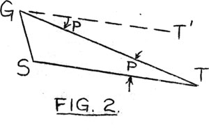
8. Parallax is the apparent displacement of an object due to
observing it from some point other than the standard point. In Figure 2 let target T be observed
from G, and let S be the standard or reference point. GS is called the base line. Draw GT' parallel to ST. As viewed by an observer at G, T will appear further to the
right than it would by an observer at S, the reference point. The angle of apparent displacement
is
--11--
T'GT = P. Therefore the parallax observed
from any point equals the angle between the line from that point to the target
and the line from the standard or reference point to the target.
9. The line joining gun and director is rarely either horizontal or
vertical. For convenience, parallax
is divided into two components:
Horizontal (i.e., base line along the deck). Vertical (i.e., base
line perpendicular to deck).
Vertical parallax must not be confused with director-correction.
Horizontal Parallax.
10. Any gun not in the same vertical line with the gun director will be subject
to errors due to Horizontal Parallax, which may be defined as the angle in the
horizontal plane between the lines of sight of gun and director when they are
both on the target.
--12--
11. Referring to Figure 3, it will be seen that the horizontal
parallax angle is a function of two
variables, range and bearing,
and that each gun will require its
individual correction. Bearings
are measured with respect to the
line joining gun and reference point.
12. Each battery has a reference point to which all
horizontal parallax corrections are made.
Usually it is at the center of
rotation of the most important
director. Not only must each gun
be corrected to this point, but also
other directors, unless
their horizontal distances from the
reference point are negligible.
13. Except
in the Sperry system, horizontal parallax is corrected mechanically at each director, gun
station or turret, the
corrector consisting of some mechanism which will solve the
parallax formula, or a close approximation of it. Gun train is
assumed equal to bearing as an input to the gun correctors.
Range is usually introduced by hand.
14. In the Sperry system the correctors are in instruments in
the plotting room, and relative bearing is used.
15. In the Maryland Main Battery Type installations the correctors
are located in the turrets, but the range, input to all
correctors
comes from a transmitter in the plotting room.
16. In
the Vickers system the horizontal parallax mechanism
is called the "Convergence" mechanism.
Vertical Parallax, Surface Target.
17. In correcting for vertical parallax for a surface
target it is assumed that gun and target are
on the same level and that
the director is directly above the
gun. This simplifies the
parallax equation to:
sin P = p
where P is the parallax angle, h the
height of the director above the gun in yards, and R the range in yards. Since Iris
constant, R is the only variable, and the corrector may be simple.
18. Some main battery installations have no
correctors. It.
is easy to prepare a table or curve
showing the corrections at all
ranges. The proper correction may
be picked from this table or curve
and applied to the advance range as a ballistic correction. Broadside battery directors have range
(sight) scales with
graduations which are corrected for
vertical parallax. Some main
battery directors have a device
which moves the director pointer's
telescope without changing the
transmitted director correction. Some installations have range converters
which are graduated to include
the correction.
--13--
19. Usually all guns of a battery are assumed to be at the
same level. Guns never have
individual correctors. (Excepting
Vickers
installations). Instead, the
directors are corrected to
"mean trunnion height."
20. Provision is made for correcting for individual gun heights
in the
Vickers installation. Vickers
literature uses the term
"dip" in place of "vertical parallax". As a matter of fact
vertical parallax equals the difference in dip from the horizontal
to the target, as
measured at the two heights.
Vertical Parallax, Air Target.
21. As shown in the accompanying figure, vertical parallax may
be partially caused by a horizontal base, when the target is elevated.
Erosion Correction.
22. As a gun is fired it wears or erodes, resulting in gradual reduction in
muzzle velocity, and corresponding loss in range. For a given gun the velocity loss is a function of the muzzle velocity and
of the amount of erosion. The
amount of erosion
may be expressed in terms of "bore enlargement" or of
"equivalent service rounds fired.7' Bore enlargement is now preferred as a measure
of wear. The Proving Ground has
collected data
and issued curves showing the approximate velocity loss to be expected, at
standard and at reduced velocities, for any value of bore enlargement
(or of equivalent service rounds). From such-data a ballistic correction may be computed and applied to the advance range. It is well to note however that guns
which have the same amount of bore enlargement may give rather wide differences in
--14--
velocity loss. The same is-true to a greater extent in the case of guns
having fired the same number of equivalent service rounds.
23. If all the guns of a battery are eroded
about the same it is easy to correct for the resulting velocity
loss. But if there are wide differences
between guns it becomes imperative to allow for the differences in velocity,
therefore
provision is usually made for applying individual corrections to each gun,
except where there are two or more guns in
a single slide. In general this correction is introduced into the gun
elevation indicator in such a way as
to cause the gun to be elevated the required additional amount.
24. The latest practice is to provide a simple crank which is attached
to a dial graduated in minutes of arc. The dial is set for the computed
angular correction for that gun for the firing range.
The crank applies an offset to the indication of its indicator, causing
the gun to be elevated a little more.
25. For main batteries of battleships (except modernized
battleships), the erosion corrector is a part of the Elevating
Gun Attachment. A schematic
diagram of this corrector is shown
in Plate 2. "Rounds fired" is
set by hand on the graduated scale
by means of the adjusting screw shown. "Director Correction" is
set by hand. This value is introduced in order that the elevation
angle above the deck which is received from the gun may be
changed to equal the gun elevation
above the horizontal plane
(i.e. sight depression), which is a
function of the range. Thus
the range input is automatically
introduced. With the pointer
set at a given angle corresponding
to the number of rounds fired,
the sight depression ("range angle") introduced through the erosion
corrector screw, causes the erosion corrector plate to slide
backward or forward along the guide bracket. This movement causes
vertical movement of the rack equal to the erosion correction.
The rack applies the correction to the gun elevation
input of the elevation indicator. The
quantities which the shafts represent as shown on the plate are for the
condition when the elevation indicator is matched.
26. In the G.E. broadside
installations erosion correction is
introduced by means of the Erosion and
Parallax Adjuster located
on each of the gun mounts near the
sightsetter's station. Rounds
fired and range are set by hand and the mechanism is such as to
transmit mechanically to the Elevation Repeat Back the proper
elevation correction.
Range differences due to horizontal separation of guns.
27. Due to their horizontal
separation if all guns of a battery
throw their
projectiles the same distance, the projectiles will
--15--
will land at different distances from the firing
ship (unless they are fired abeam). For guns closely grouped, this error is negligible but for
a battery the units of which are widely separated
it may be appreciable. This error
has been called "horizontal parallax in range", a
misleading terra.
28. Consider the conning tower of
a battleship to be the reference point for its
main battery. If the turrets were
firing
dead ahead, #1
and #2 would be firing over and #3 and #4 would
be firing
short. If the turrets were all at
the same height the
error in each case
would be (theoretically) the distance from the
reference point to
the turret considered. This error
in yards is
constant at all
ranges for a given angle of train, assuming all
guns to be on the same level. But
the angular correction
necessary to
compensate for a given range error varies with the range.
Therefore the
angular correction is a function of both angle of
train and range.
29. "In a few installations
provision was made for correcting
for this source of error. These
correctors proved unsatisfactory
because they introduced
lost motion which sometimes exceeded the
correction. Some ships use their
roller path correctors to
introduce a correction for mean battle range. If "his is done the
error at other ranges is partially corrected for. The method is
called "Phantom Roller Path Correction". It is described in
FTP 134, Art.1640. The method is simple, and causes no additional
lost motion.
Trunnion Tilt.
30. If the setting of a gun in
elevation is to be entirely in
the vertical plane and the setting in deflection entirely in the
horizontal plane, the trunnions of the gun must lie in the
horizontal plane. This condition
is realized with the ship in normal
trim and on an even keel, but as the ship rolls and pitches the
plane containing the trunnions is inclined and this inclination
will normally have
components both in and-across the line of fire.
It is the
component across the line of fire which causes the
trunnions to be
tilted.
31. Referring to Plate 3, it will be seen
that the effect of trunnion tilt is in general
to reduce the range of the projectile and
to cause a lateral deviation of the projectile to the same side
as that toward which the gun is tilted. Within the limits of trunnion
tilt encountered in practice, the
effect on the angle of elevation is
small and might be neglected, without material error. The effect on
deflection at long ranges is, however, too great to be neglected.
An approximate rule for determining the
deflection error due to trunnion tilt
is as follows: the deflection
error in minutes, due to trunnion tilt, is equal to the
--16--
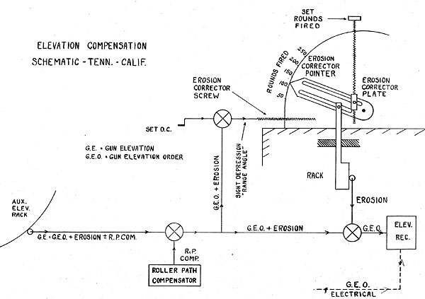
Plate 2
angle of elevation in degrees times the trunnion tilt in degrees.
32. It is to be noted that trunnion tilt causes the same errors
in
pointer fire as, in director fire, but that it is almost
impossible
to correct them in pointer fire.
33. There are two general methods of correcting errors due to
trunnion
tilt in director systems: (a) the
use of a "dummy gun"
and
(b) the use of a computing mechanism.
34. The "Dummy Gun". This system is used in General Electric
secondary
battery installations and in Lexington and Saratoga
main
battery installations. It consists
essentially of a "dummy
gun" (a part of the gun director, also called "gun pilot") and
a cross-leveling mechanism. The movement, of the dummy gun in
reference to the deck is transmitted to the
guns as Gun Elevation Order and Gun Train Order. If the director
were not equipped with a cross-leveling
mechanism to correct for trunnion tilt, these transmitted signals would be
incorrect in both train and elevation for any condition of cross-roll.
35. With the cross-leveling mechanism in use, a means is
provided
for correcting this error. Motion
of the cross-leveler's hand wheels as he maintains his line of sight on the
horizon 90° from the line of fire move the telescopes of the pointer and trainer in reference
to the dummy gun in such a direction and amount as to cause correction of the
cross-roll error when the director line of sight is returned
to the target. (See O.P. 471 and 110 for more
detailed explanation of this method.)
36. The Computing Type T.T. Corrector. In this method the
necessary
corrections in train and in elevation are mechanically
computed
in a cross-roll or "trunnion tilt" corrector. The
corrector
receives flange, Deflection, and Cross-Roll Angle. It
computes
the proper corrections. Since the
cross-roll error in
elevation
is relatively small, it is neglected in the later
installations. The computed, corrections are applied
in various ways. For more detailed,
descriptions see the description of the
"Consolidated" system.
--17--
Table of Contents
Previous Chapter (1)
Next Chapter (3)
Transcribed and formatted by Thomas Wildenberg


 7. The Vickers director is equipped with a compensator of
similar type which offsets the telescope. Other directors have
no
compensators but are adjusted as nearly parallel to the standard plane as possible by
means of three equi-spaced adjusting
bolts in
their bases.


