
CHAPTER 3.
TRANSMISSION SYSTEMS.
1. At the
present time the United States Navy uses, to a greater or lesser extent, the
following systems for the transmission of fire control information:
| 1. Sperry (Train only) |
} |
Installed in conjunction with each other. |
| 2. Ford (Elevation only) |
| 3. Vickers |
| 4. General Electric (Selsyn) |
| 5. Ford D.C.S. (Direct current, synchronous) |
| 6. Arma. |
2. Some of
these transmission systems differ only in details of design, whereas others are
based upon radically different electrical principles. In this chapter
each of these systems is briefly discussed,
with the object of enabling the student to group readily its underlying
electrical principle, and such other features as will assist in a clear
differentiation between the several systems.
Sperry Transmission.
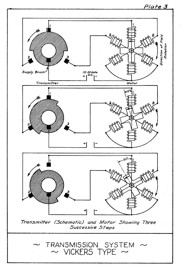
3. This system
of transmission was developed a few years
prior to the World War, as the result of collaboration between
the Navy Department and the Sperry Gyroscope Company. Fire con
trol installations using this type of transmission were limited
to main battery control in train only; but somewhat later the
Ford Instrument Company designed a companion transmission system
for control in elevation. As a
result, these two transmission
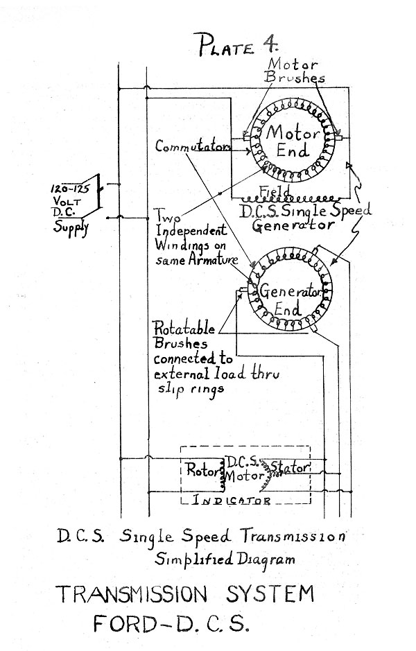
systems are almost always found installed in conjunction with
each other, but as each utilizes a different method of transmis-
sion they will be described separately.
4. The Sperry
system of transmission is a step-by-step system
operating on direct current (20 volts), and is not self-synchron-
ous. The operation of the
transmitters originates successive
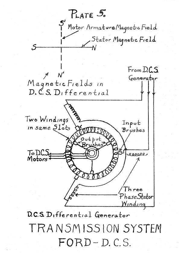
electrical impulses which cause motors in the indicators to follow
step-by-step, i.e., one step for each impulse. In order that the
indicators can duplicate the readings of the transmitters it is
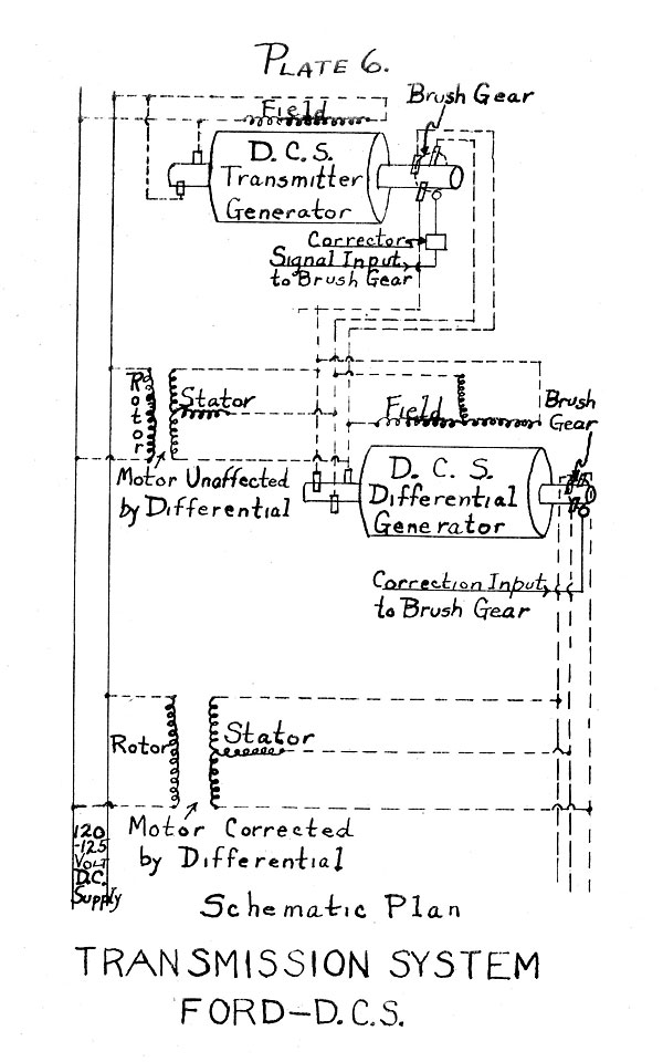
necessary, each time the system is placed in operation, first to
synchronize the system by setting each indicator manually to the
reading of its transmitter. Synchronization must be repeated each
time the current supply is interrupted, unless it is certain that
none of the transmitters have been moved while current was off;
for if a transmitter is moved while the current is off, the indi-
cators cannot follow, and when the system is again energized the
indicators will be out of step with the transmitter and will remain
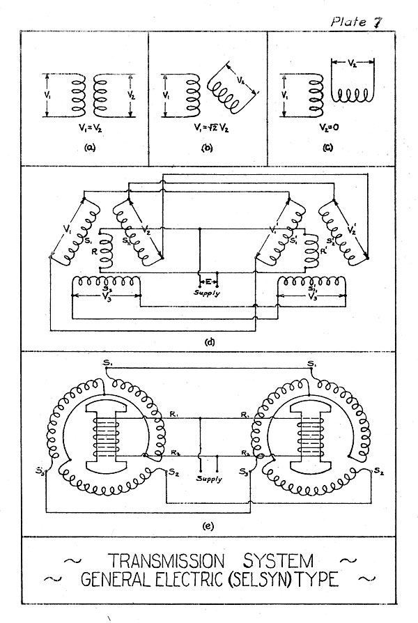
--18--
so until again synchronized by hand. Similarly, it is necessary to synchronize the system when
shifting from one transmitter to another.
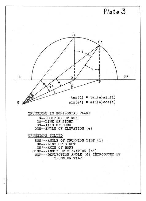
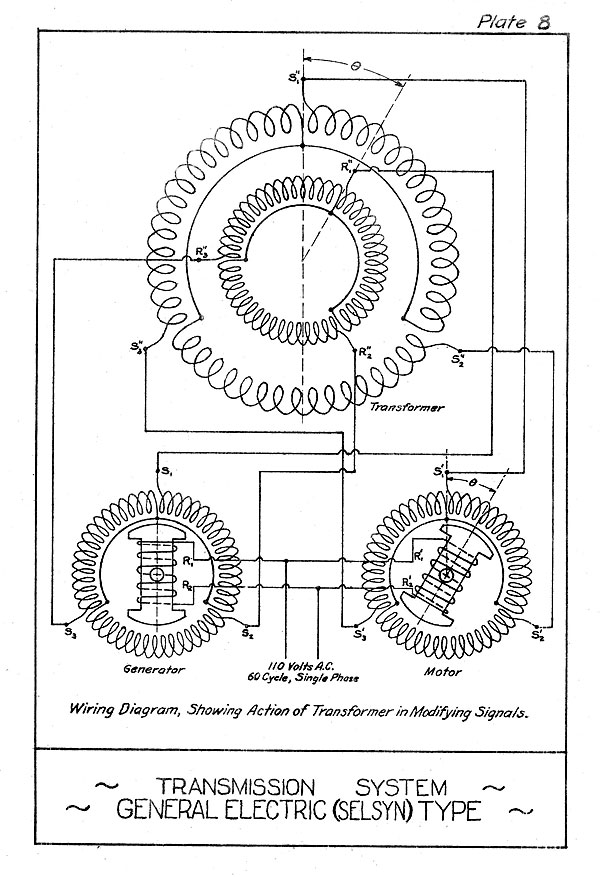
5. The accompanying diagram (Plate 1) indicates the electrical
operation
of the Sperry transmission. It
shows the two types
of transmitters, the single transmitter at the top and the double
transmitter
at the bottom. For simplicity,
each is shown wired
to the motors of only one indicator.
6. The single transmitter has three contact fingers, from one
side of
which three wires are run to the three pairs of poles of
the step-by-step motor. The other
sides of the three contacts
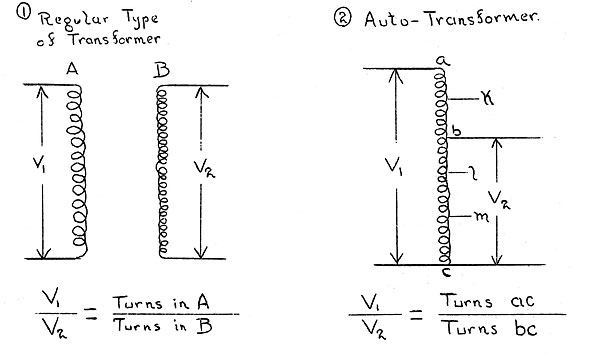
are connected together and to one of the SO volt supply lines.
The other supply line is connected to the common side of the
motor field coils. Thus the separate
field coils are energized
only when the transmitter contact to which they are connected is
closed. There is no electrical
connection to the laminated iron
armature, which is moved simply by the magnetic pull of the field coils.
7. The contact fingers on the transmitter are raised and lowered in proper
sequence by revolving cams mounted on the same
shaft and spaced at angles of 60 degrees. Starting with No. 1
contact closed and Nos. 2 and 3 open, the motor armature will,
since No. 1 coils are energized, take up the position shown,
standing opposite No. 1 pole. If now we go
forward, the next step
will be with Nos. 1 and 2 contacts closed (No. 3 open) and-
motor armature in position half way between Nos. 1 and 2 poles;
the next step, No. 2 closed Nos. 1 and 3 open; and so on, through
the twelve different armature positions (steps) in a complete
revolution of the transmitter cam shaft. If
the transmitter
shaft is turned, continuously in one direction the motor armature
will follow at the same speed in the same direction. When the
transmitter shaft is reversed the armature will also reverse and
follow in the opposite direction.
The double transmitter consists of two
sets of contact fingers, actuated by a single cam shaft but connected to
two motors.. By means of this arrangement twice the number of steps is obtained per
revolution. This is accomplished
by gearing the two motor armatures together and having the two motors oppose
each other on alternate steps.
8. Double transmitters are used in parts of the system where
greater accuracy is necessary, but with both types the gear ratios
are usually so designed that one step of transmitter and motors
corresponds to 5 minutes of arc.
9. The indicators of this system are of the follow-the-pointer
type, that is, the motor armature shaft moves a red pointer
--19--
around a dial,
whereupon the turret trainer moves his turret until a second
(white) pointer, actuated by the train of the turret, is matched
up with the red pointer of the indicator.
10. Miscellaneous features of this system of transmission are:
(a) Provision is made for setting all transmitters on an
"electrical zero", so that if a transmitter has
to be dismounted it can readily be lined up when reinstalled.
(b) The torque on the motor armatures is amply sufficient
to hold the indicator pointers steady when the transmitter
is at rest.
(c) If a motor armature should become "stuck" or jammed in
any manner, it will not affect the electrical impulses sent to
the other motors by the same transmitter.
11. The principal advantage of this system is that it is
electrically simple. Its disadvantages are that
it is not self-synchronous, the necessarily limited number of steps do not permit
an absolutely smooth and continuous following of the target,
and the design of material is not as rugged as could be desired.
Ford Transmission.
12. The Ford system of transmission is a step-by-step system
operating on direct current (20 volts), and is self-synchronous
within its-range of operation. Unlike the Sperry
transmission, which must operate
throughout 360 degrees of arc, the Ford
transmission merely has to function within an arc which is limited
approximately by the maximum angles of elevation and depression
of the main battery guns, or in the
neighborhood of 35 to 40 degrees. Because of this limited range of
operation it is possible to construct a simple step-by-step system which
is also self-synchronous.
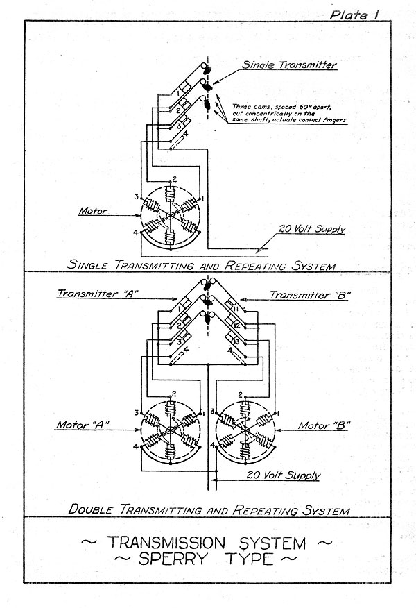
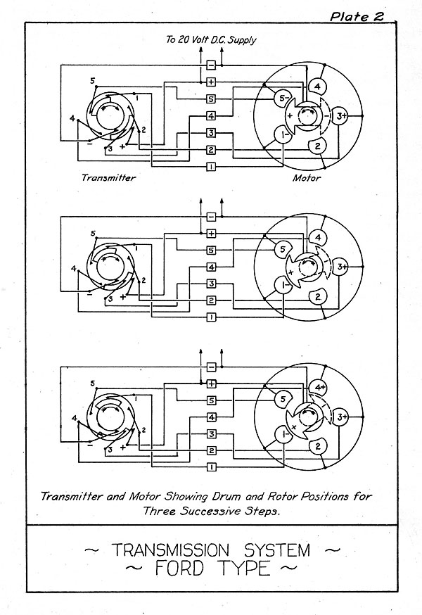
13. The electrical features of the Ford transmission are
shown on the accompanying diagram (Plate 2) which shows one
transmitter unit wired to one motor. The essential difference
between this system and the Sperry system is that a wound rotor
is used in the motors instead of a
plain iron armature. This rotor
consists of two iron vanes, one above the field coils and one
below, with a coil wound about the rotor shaft between them. The
ends of the coil are connected to the supply line in such manner
that the upper vane of the rotor is always positive and the
lower one negative. This gives the
rotor directional characteristics which cannot be obtained
by the simpler Sperry armature.
14. The transmitter consists of a four-quadrant
contact drum, one quadrant of which is always positive and the opposite one
--20--
negative, while the two quadrants in between
are cut away in order to "break contact. Five
contact fingers, wired to the five
motor field coils, are equally spaced about the transmitter
drum so as to make contact alternately with the positive and
negative quadrants as the drum revolves.
15. Each motor field coil is wound in two sections,
the upper half being wound in one direction and
the lower half in the opposite
direction, so as to make both ends of the pole have the
same polarity when the coil is energized.
16. With this combination of a rotor with constant magnetic
polarities and field coils in which the polarities can be varied
at will, a finer control of steps is possible, and twenty steps
are obtained per revolution instead
of only twelve steps as with
the Sperry transmission. However,
as these additional steps are
not sufficient to give one
transmitter the necessary range of
self-synchronous operation, the
actual transmitting- units of the
Ford system consist of two or three
transmitters with their
drums interconnected through a
mutilated gear and transfer
mechanism. In this way the first (units) transmitter, drum makes a
complete revolution before the second
(hundreds) drum makes one
step. For the director-correction
transmitter the steps of the
units drum represent 5 minutes of
arc, and the steps of the
hundreds drum represent 100 minutes. For the gun elevation
indicators the steps of the units
drum are 2-1/2 minutes, those
of the second transmitter drum 50 minutes, and a third (three-position) drum makes
one step for each 1000 minutes, Through these arrangements
the Ford transmission becomes self-synchronous
within its designed range of operation.
17. The indicators of this system are of the follow-the-pointer
type, with the addition of windows in
which appear numbers
showing in minutes the transmitted
angle and the actual angle
set on the gun or range converter.
18. Miscellaneous features of this system are similar to the Sperry
system, i.e., index marks permit setting, transmitters on "electrical
zero", the motor torque holds pointers steady while the
transmitter is at rest, and a "stuck" motor will not affect electrical
impulses sent out by a transmitter.
19. The advantages of the Ford transmission over the Sperry are that
it is self-synchronous and the material design is
considerably more rugged. Electrically it is almost as simple. In common
with the Sperry system it has the disadvantage of being
a step-by-step system, "but for
the usual conditions of director fire this feature is of little consequence
in an elevation system.
--21--
"Vickers Transmission.
20. The Vickers system of transmission was devised by the
British. During the World War we
adopted it for use in the director
systems of the secondary batteries of
our battle ships, and later
it was extended to the main battery control of light
cruisers and gun control of destroyers.
21. It is a step-by-step system, operating on 15 to 20 volts
direct current, and is not self-synchronous. The transmitter is
very compactly arranged, with three contact brushes and a supply
brush grouped in pairs on either side of a rotating drum. The
supply brush bears continuously on the drum, but by means of two
180-degree segments cut out of the drum, the other three brushes
have their contact made and broken in proper sequence. In the
accompanying diagram (Plate'3) the transmitter arrangement is
shown somewhat altered for the sake of clearness, but the order
of brush contact is identical with-that of the actual transmitter.
22. The motor is a six-pole motor, the field of which is
wound in the same manner as the Sperry motors. However, the
plain iron armature is made in the shape of a cross, and-in this
feature, and in the resulting operation, the Vickers motor
differs from the Sperry. The Sperry armature permitted only twelve
armature positions per revolution for a single motor, whereas
the Vickers armature gives twenty-four steps per revolution
without making the motor any more complicated.
23. It can be seen from the diagram that with the cross type
of armature the direction of motion of the armature is opposite
to that of the direction of energization of the field coils,
whereas in the Sperry transmission the armature and field both
rotated in the some direction. Another difference is that the
Vickers transmitter drum makes four complete revolutions for one
revolution of the motor armature, while the shaft of the Sperry
transmitter makes only one revolution for each revolution of the
motor armature.
24. The Vickers indicators (generally termed "receivers") are
of the follow-the-pointer type. Synchronization in train is
done by hand, while the elevation system is synchronized by
elevating and depressing the director against top and bottom steps,
in this way bringing all the red elevation pointers into agreement
with the director. The gear ratios used give the following values
for steps:
1 step of slewing transmitter = 1 degree of train
1 step of training transmitter = 2 minutes of train
1 step of elevation transmitter = 3/4 minute of elevation
--22--
25. The Vickers system is electrically simple; all transmitters
are identical arid all motors are Identical, and so are interchangeable
throughout the system; the control in both train and elevation
is finer (smaller steps.) than with either the Sperry or Ford
transmissions; and the material design is quite rugged. In
common with the two preceding transmission systems, it has index
marks for lining up the system,- sufficient motor torque to hold
pointers steady, and freedom from transmitter disturbances due to
a "stuck" motor. Its principal disadvantage is that it is not
self-synchronous.
Self-Synchronous Systems.
26. Although the Ford Elevation system, which has been described, is
self-synchronous, the term "self-synchronous system" is habitually used
to mean a system which is not only self-synchronous but which can
also transmit an infinite number of
steps. At present three such installations are in use:
| The Ford DCS System: |
|
(Not to be confused with the Ford Elevation System)
Manufactured by the Ford Inst. Co. |
| The Selsyn System: |
|
Manufactured by the General Electric . Co.
|
| The Arma System: |
|
Manufactured by the Arma Engineering Co. |
27. Future installations will be of the "Synchro" type.
"Synchro" is a trade mark registered by the Bureau of Ordnance, and is used to
designate a system which is completely described
by Bureau of Ordnance specifications. In principle the
"Synchro" system is identical with the "Selsyn" system, but any manufacturer
may manufacture it, the G.E. patents having expired. The advantages
of this procedure is that in future contracts it will merely
be necessary to specify that the "Synchro" system be used: the
specifications for the "Synchro" system
completely defining the system and the conditions it must fulfill.
28. Zero-Reading Instruments. Prior to the introduction of
the first self-synchronous system (GE Selsyn system) indicators
were of the follow-the-pointer type, i.e., the indicator had two
sets of pointers. One set was
positioned by the distant trans-mitter while the
other set was moved by the gun. Beginning with
the Selsyn transmission system the "zero-reader" type of
indicator came into use. In this type a moving dial has a pointer.
The arrangement is such that when this pointer is brought to a
fixed reference line, the gun is properly oriented. In other
words, the zero-reader, when on zero, indicates that the difference
between the signal received and the gun's angular position
is zero. The zero reader type of indicator was used exclusively
for years in all new construction. Now, however, the follow-
--23--
the-pointer type is again being used in many places,
notably on the fine dials of train indicators.
29. Coarse and Fine Dials. Where accurate indications are
necessary and the self-synchronous feature is to be retained,
two generators, motors, and indicating dials are used. The
"coarse" dial indicates large changes and the "fine" dial small
ones. The coarse dial has a different position for every trans
mitted signal, thereby retaining the self-synchronous feature.
A single position of the fine dial may mean any one
of a number of angular positions of the transmitter, but it
indicates accurately what the coarse dial shows approximately.
DCS (DIRECT CURRENT SELF-SYNCHRONOUS) TRANSMISSION SYSTEM.
Note: Although this system is described first, it was developed after the Selsyn system.
30. SINGLE SPEED TRANSMISSION: A typical case of a single
speed DCS generator transmitting to several DCS motors is shown
in Plate 4. The generator has a single rotating armature with
two independent windings - one a motor winding, the other a
gen-erator or transmitting winding. The motor is connected to the
D.C. supply circuit by means of a commutator and two brushes.
The field, which is stationary and common to the two armature
windings, is connected across the two motor brushes.
31. The generator or transmitting winding on the armature is
connected to the generator commutator on which there are
three brushes spaced 120° apart. The brushes are mounted on a gear
driven ring so that by means of a mechanical input they can be
rotated around the commutator to a position representing the
quantity to be transmitted. The three brushes are electrically
connected through slip rings to external wires leading to the
stators of the DCS motors in the indicators to which the signal
is to be transmitted.
32. The motor has a three phase stator winding and a single
rotor winding. The latter is connected through slip rings to
the D.C. supply circuit. A number of motors can be connected in
parallel to one generator. A motor may be made with rotable
stator for zero reading indicators.
33. Principle of Operation: In the DCS generator the action of
the motor winding and the common field is to drive the armature
as a motor. The other armature
winding in conjunction with the common field acts as a generator.
The generator brushes are rotated around
the commutator by an external mechanical input in accordance
with the quantity which it is desired to transmit. While the brushes are in
motion-the voltage between any two
--24--
brushes varies as a sine wave, so that
there are three sine wave voltages. These are displaced 120
electrical degrees as in three phase alternating current
transmission, but the voltages vary only
while the brushes are being moved. For any given position
of the brushes the three voltages are
constant (not equal).
34. In the motor the three voltages acting in the three phase winding
set up a magnetic field which rotates with the rotation of the transmitter brushes
and is at all times in a position
corresponding to that of the brushes. The rotor of the motor,
being excited by direct current follows the magnetic field of
the stator. The rotor may carry a dial to indicate its position
or it may control electrical contacts in a clutch or motor
follow-up circuit by means of which the received signal is given
sufficient power to drive the desired mechanism.
35. DOUBLE AND TRIPLE SPEED GENERATORS: In order to increase
the accuracy with which a signal can be received, it is
frequently desirable to transmit it at so called "high" end
"low" speeds. The low speed maintains the self-synchronous feature by
making only one revolution or
a fraction thereof for the complete range of signals.
At the generator the high speed is geared at 36 or 14 to 1
with the low speed. In the indicator
there is a motor for each speed, the high
speed motor giving a fine reading or a fine control.
The double and triple speed generators
can also be used in transmitting two or three independent
signals at single speeds. These generators are the same as the single speed machines except that
there is a set of three generator brushes for each speed,
the commutator is larger to accommodate the extra sets
of brushes. Provision is made of
course for rotating each set of brushes in accordance with the signal to be transmitted.
36. CORRECTOR: In changing the direction of rotation,
hysteresis causes a slight lag in the magnetic field of the motor. This
is compensated for by a device in the generator called a "corrector".
It is placed between the input shaft and the brush gear. It is placed
between the input shaft and the rush gear. When
the direction of rotation of the input shaft reverses,
the pinion driving the brush gear is given an axial
motion in- addition to its rotation. This results in a small additional rotation of the brush
gear so that the brushes are advanced a slight amount-beyond the correct
position of the rotors of the DCS motors to which the generator is
transmitting. This is just sufficient to compensate the hysteresis lag in the motor.
37. If the generator is to operate with a DCS differential
the corrector introduces sufficient compensation for the
hysteresis lags in the differential as well as the motors conneced to it.
--25--
38. DCS DIFFERENTIALS. The purpose of a DCS differential is to
modify the transmitted signal before it reaches the motors. For
example it could be used to apply deflection to relative
target bearing to obtain and transmit gun train order. The DCS
differential generator is shown schematically in Plate 5. It has a
three phase stator winding connected by three wires to the
transmitter brushes of a DCS generator. This sets up a magnetic field in
the stator represented by the line NS. This field is stationary
when the transmitting brushes are stationary and when the
position of the latter is changed (as in changing the angle
transmitted) the stator field changes accordingly. in other
words, the stator field of the differential rotates with the
transmitter brushes of the generator.
39. The armature of the differential has two continuous windings
each connected at numerous points to its own commutator. Three
stationary input brushes, spaced 120° apart on one of the commutators,
are connected to the same three wires that feed the
stator. The magnetic field thus set up in the armature is rep
resented by the line N'S' and is always 90° displaced from the
stator field. The forces of magnetic attraction and repulsion
between the armature and stator magnetic field cause the
armature to rotate. But due to the fact that different commutator
bars are continuously coming under the brushes, the magnetic field
of the armature remains fixed at 90° displacement from the
stator magnetic field.
40. The second winding on the differential armature is wound
in the same slots as the first. Spaced 120° apart around the commutator
of the second winding are three output brushes. They are
mounted on a common brush holder ring so they can be rotated, and
they are connected through slip-rings to one or more DCS motors.
41. If the output brushes are in the same position as the
three input brushes, the voltages of the output current will be the
same as that of the input current, and the connected DCS motor will
indicate the same angle as transmitted from the generator.
But, if the output brushes are rotated so as to be displace
say 30° from the position of the input brushes, the resulting angle
transmitted by the differential will be 30° greater or
30° less than the angle sent out by the generator. The output
angle v/ill be greater if the output brushes are rotated in the
same direction as the generator brushes are rotated for
increasing angles and vice versa. Plate 6 shows schematically
how a differential is connected in the system.
42. Advantages claimed for the system.
(a) The System operates on direct
current which is available on all ships. The present instruments
are designed for 120-125 volts. The DCS system can be designed for any
DC voltage available and for different supply voltages for motor and
transmitter.
--26--
(b) The operation is self-synchronous in all respects.
(c) If one motor is held out of synchronism by mechanical
means the remaining, motors, even though operating from the
same transmitter, will not be affected.
(d) The motors are very strongly self-damping so that oscillations
of the dial are damped out at once without the use of
a mechanical damper. There is 'no vibration point at which
vibration or oscillation is continuous.
(e) Since the fields of the motors are energized with direct
current there is no speed at which the motors when given a
rapid acceleration will
continue to spin as single phase synchronous motors, and therefore no
special damping means need be provided to prevent such action.
(f) The stator current is the same whether the rotor is in
synchronism or not. Hence in throwing a number of motors on a
transmitter there is no current surge. This makes it possible
to protect the circuits by fuses, which can be small enough to
offer protection since they do not require added capacity to
withstand current surges. The current taken by a DCS differential
while it is coming up to speed is greater than when it is at full
speed. Consequently if a differential is connected between a
generator and the motors, the fuses protecting the differential
circuit must be larger than required for the normal load.
(g) The absence of current surges makes it possible to
throw over from the normal DC supply to an emergency supply by
automatic or other quick-acting means without providing overload
capacity in the supply circuit.
(h) The transmitting circuit is independent and completely insulated
from the D.C. supply circuit, so that grounds on transmission
circuit will not affect the D.C. supply line; also a single
ground on the transmission line will not cause short-circuits
or other troubles.
(i) The two-speed and three-speed transmission is obtained from
a single small transmitting unit, thus saving the cost and space
requirements of using two or three individual transmitters.
(j) The rotors of indicators need not be energized from the
same source that is supplying the transmitter so that the number
of wires from the transmitter to the indicator may be reduced to
minimum as the indicators can be energized from a local source
of supply.
43. Disadvantages of the System:
--27--
(a) Both the "generator" and the "differential" are in
motion continuously when the system is energized, regardless of
whether a change in signal is taking-place or not. This causes
relatively short life and more chance of trouble with these
units as compared with the Selsyn and Arma units, in which there
is mechanical motion only when a change in signal is taking place.
(b) The "generator" and "differential" have commutators,
which give more trouble than slip rings.
(c) The system is not quite as accurate in indicating trans
mitted signals as the Selsyn and Arma systems.
(d) More power is required to operate the system because
current flows from the "generator" to the "motors" constantly,
while in the other systems this is true only when a change in
signal takes' place.
THE SELSYN SYSTEM.
44. "Selsyn" is the trade name applied to the General Electric
transmission system and means "self-synchronous". The system
operates on A.C. using about 110 volts, single phase, 60 cycle
alternating current.
45. There are four types of selsyn units, named according to
their uses, as follows:
(a) Selsyn Generator - which transmits.
(b) Selsyn Motor - which receives and indicates.
(c) Selsyn Transformer - which may be inserted between a
"generator" and a "motor" in order to modify the transmitted
signal. For example, a transformer may be used for applying
deflection to relative target bearing in order to obtain gun order.
(d) Selsyn Differential Motor - an indicator which shows
the difference between signals transmitted by two generators.
46. The terms "generator" and motor" are misleading because
they do not function electrically like generators or motors, in
spite of the fact that they are constructed like two pole
3-phase alternators. Electrically the "generator" and the "motor"
are the same. The only difference between them is that in the
"motor" the rotor is free to turn, while in the "generator" the
rotor is mechanically restrained and is placed in a definite
position .corresponding to the signal it is desired to transmit.
47. Electrically the two instruments follow the principles
of transformer action. When a pair of them are connected and
energized, their rotors are the primaries and are both excited
by the same power source. Their stators are the secondaries and
are connected to each other. If the rotors are in the same positions relative to
the stators, the same voltages will be induced in
both stators. In this case the voltages "buck" each
--28--
other and no current flows in the secondary (stator)
windings. But if the rotors are not in the same positions the
secondary (stator) voltages will be unequal and current will flow in
the stator windings of both instruments. Because these windings carry
current and are in the fields set up by the primaries (rotors),
there will be a force between the stator and the rotor of
each instrument, i.e., a torque will act on both. The "generator's" rotor is
constrained and can not be moved by this torque,
but the "motor's" rotor is free to turn and will turn in such a direction as to
reduce the torque. When the
"motor's" rotor is matched with the "generator's" rotor, the "motor" is in synchronism and the
stator voltages are balanced, so that no current flows and
consequently there is no torque.
48. The student who has had little schooling in alternating
current theory should-not throw up his hands in dispair of
understanding the selsyn principle. He should reread the last
paragraph and tnen study the following paragraphs which describe
in detail how the instruments function.
49. Plate 7, figure (a) shows two equal transformer windings
parallel to each other. In this case the secondary voltage
equals the primary voltage, i.e.(using
the subscript 1 to
designate the primary, and 2 the secondary):
Y1 = V2
In Figure (b) the windings make an angle of 45° with
each other. In this case the secondary voltage will be the
primary voltage times the cosine of the angle which the windings make with each
other, i.e.:
V1 V2 = V1 cos 45° = √2
V1 = √2 V2
If the angle between the coils is, 90° as in figure (c), then:
V2 = V1 cos 90° = 0
In
other words, there will be no induced voltage.
50. In Figure (d) two sets of three
transformer secondaries are arranged in the form of equilateral triangles, the
corresponding secondaries being connected together. A coil (R,' R') is placed
in the center of each triangle and connected to" a single phase
A.C. -source. If R and R' are not parallel when the A.C. current
is turned on, the voltages set up in the coils, S1, S2,
--29--
S3,S1', S2', S3'
will not be equal (although they will be in phase),
and currents will flow in the leads connecting the two sets of
transformers. These currents would
set up a flux in the secondary coils which would conflict with the magnetic
fields set up by R and R' and therefore induce a torque on the coils
R and R* so that if they were free to turn they would do so. When R and R' had turned to
a position in which the direction of their flux fields
were parallel, the voltages V1,
V2, V3 would equal V1', V2', V3'
respectively, and no current would flow in the coils, so
that no further torque, would be induced on Coils R and R' and
they would cease to turn.
51. Figure (e) (Plate 7) shows the actual arrangement of the
Selsyn System. One of the sets of transformers is called a
generator, the other set is the motor. The secondaries are
wound on the stator and connected "Y" so that only three leads
instead of six are required to connect the secondaries of the generator and motor. (The windings
could be connected "A"). The coils R and R* are wound on the rotors of the generator
and motor and are connected to the same A.C. supply. The generator
rotor is mechanically geared to a transmitting instrument
and its motion is thereby restrained by the transmitting
mechanism. The rotor of the motor is free to move and follows
in synchronism with the rotor of the generator.
52. Selsyn Transformer. The Selsyn Transformer is a device
for introducing an angular change into the output of a generator
before it enters the motor, so that the reading of the motor
indicator will be that of the generator + the change introduced by
the transformer. This is accomplished by having the rotor as
well as the stator wound with three circuit windings. See Plate 8.
53. The set of three voltages from the generator impressed on
the transformer rotor produces exciting currents which produce
an alternating magnetic flux. The direction of this flux with respect to
the transformer rotor leads R1", R2", R3",
is the same as the direction of the generator rotor flux
with respect to the generator stator leads S1,
S2, S3. This flux induces a set of
three voltages in the three transformer stator circuits. When
the transformer rotor windings are in the same positions as the
transformer stator windings (i.e., when R1", R2",
R3" are
adjacent respectively to S1", S2", S3"), the voltages across
S1", S2", S3" are the same as
those across S1, S2, S3. In
this case the output signal from the generator is not modified by the transformer.
54. The transformer stator voltages maybe changed either by
turning the rotor of the generator with the transformer rotor
mechanically restrained, which turns the transformer flux by
--30--
electro-magnetic means, or by turning the transformer rotor, which mechanically
changes, the direction of the direction of the flux.
55. The angular signal, as represented by the set of trans-former
stator voltages, is therefore the algebraic sum of the generator
rotor angle and the transformer, rotor angle. The transformer
stator voltages, being impressed on the stator of a
motor, cause it to operate in synchronism with the modified
signal, as indicated.
56. The Selsyn Differential Motor is simply a Transformer with its
rotor free to turn, which is connected between two
generators, so that the sets of voltages of one generator are impressed
on the stator and those of the second generator on the
rotor. As long as both generators are transmitting the same
angular signal, the rotor of the Differential Motor remains fixed
at its zero position, but as soon as there is any disagree-ment in
the angular signals the rotor moves off the servo position an
amount equal to the angular difference between the transmitted
signals. A dial attached to the rotor shaft indicates
this difference.
57. Exciters. When a single generator transmits to a number
of motors it carries a heavy load. In some cases it would be
necessary to use an inconveniently large generator to carry the load,
were it not for an "exciter" which: is connected to the
circuit. There are two types of "exciters". One is a large
selsyn motor immersed in oil which is connected on the line like
any other motor; but it is so wound that, under load, it produces a
slightly higher set of voltages and therefore carries most of the
load. The other type of exciter consists of a set of
condensers which are so arranged as to improve the power factor, thus
reducing the load. The first type of exciter is not
very satisfactory principally because they do not follow perfect-ly and
thus cause errors. However in later installations the
indicating motors themselves are so wound as to function like
exciters of this type, and it is believed that they will prove
to be satisfactory.
58. "Stuck" Motor. If the rotor of a Selsyn motor, in a circuit
in which there are several motors actuated by a generator,
becomes "stuck", so that it cannot rotate freely, the motor will
then operate as a generator and cause the readings of all the
other motors in that circuit to be in error. (They will indicate
half way between the generator signal and the reading of the
stuck motor.) If the "stuck" motor is removed from the
line the other motors will synchronize and the circuit will be
able to operate correctly again.
59. Damping. Motors are provided with oscillation
dampers. One type is a kind of
fly-wheel, attached to the shaft through a friction device. The other
type is a magnetic drag.
--31--
60. Advantages of the Selsyn System. Various advantages of
this system over other self-synchronous systems have been claimed.
The thing most in its favor is that it has proved satisfactory
in service.
61. Disadvantages.
(a) If one motor sticks, it throws out the other motors.
(b) The first installations have many more units than necessary.
(c) The torque is zero when the motor indicates correctly.
In spite of this, however, the indicators follow very closely
the transmitted signal.
ARMA. TRANSMISSION SYSTEM.
62. The Arma system works on the same principle as the Selsyn
system. In fact an Arma unit (generator, motor, etc.) could be
substituted for a selsyn unit and vice versa, provided the unit
substituted was designed for the same voltage, etc., and that it
would mechanically fit in place.
63. Types of Units. The Arma system has units corresponding
exactly with the four selsyn units (see Par. 45), and in addition
it has an additional kind of transmitter. The Arma nomenclature
is as follows:
(a) "Synchronous Transmitter". This is the equivalent of
the selsyn "Generator". It transmits signals.
(b) "Synchronous Indicator". This is the equivalent of the
selsyn "Motor". It receives and indicates signals.
(c) "Differential Transmitter". This is identical with the
selsyn "Transformer". It receives a signal from a transmitter,
modifies it, and transmits the resultant to a "synchronous indicator".
(d) "Differential Indicator". This is identical with the
selsyn "Differential Motor". It indicates the difference between
the signals transmitted by two transmitters.
(e) "Commutator Transmitter" which is different from the
"synchronous transmitter"(or selsyn "generator") in construction,
although it has the same electrical and mechanical inputs and outputs.
64. The only difference between the "synchronous transmitter"
and the selsyn "generator" is that the rotor and stator windings
are interchanged. That is, the three-circuit winding is on the
rotor and the single-circuit winding is on the stator. Electrically the
action is the same. Similarly, the only difference between
the "synchronous indicator" and the selsyn "motor" is that
the rotor has the three-circuit winding and the stator the single
circuit winding.
--32--
65. There is no difference (except of course in minor details
of design) between the Arma units "Differential Transmitter",
and "Differential Indicator", and the corresponding Selsyn units
("Transformer" and "Differential Motor").
66. Commutator Type Transmitter. In the selsyn "generator"
and in the Anna "synchronous transmitter" the primary and
secondary circuits are separate, one being on the rotor and the
other on the stator. In the commutator transmitter, transformer
action is also used, but it has only one winding, i.e., it is an
"auto-transformer".
An "auto-transformer" is a transformer in which part of the
same winding is employed as both primary and secondary. The difference
between an auto-transformer and a separate coil trans-former
is indicated in the accompanying figure. The voltage relationships
are as indicated. It can be seen that in an auto-transformer any desired voltage can be
obtained by connecting with taps at the proper points, such as k, l , m.
68. In the arma "commutator transmitter" the exciting voltage is put across a long
coil (which is bent into circular form for compactness). At various points this coil is tapped
and each lead
is connected to a segment of a cormnutator. The number of coils
between adjacent commutator segments is not constant however. In fact
the number of coils between commutator segments
--33--
is so arranged that if two brushes spaced 120° apart
are moved around the commutator the voltage across the brushes will
vary as a sine wave* If a third "brush is spaced 120° from the other two
brushes, there will be three voltages. If the three brushes are rotated around the commutator, the
three voltages will vary as sine waves which are spaced 120°
apart. This is precisely what
happens when a selsyn "generator" or an Arma "synchronous transmitter"
is rotated, in changing the transmitted signal._Consequently
this transmitter will function like the other types. The
signal is transmitted by positioning the set of three brushes,
69. Plate 9 illustrates the method of tapping the auto-trans
former to obtain the sinusoidal voltage characteristic as the
brushes are rotated. It will be noted that there are 360
segments on the commutator, with opposite members connected in
parallel. To these have been brought 157 taps and the two end
leads of the auto-transformer. Of course more
or fewer segments could be, used, but
the fewer the segments the larger the voltage
step in shifting the brushes from one commutator to the next.
If there could be an infinite number of commutator
segments, the three output lsecondary) voltages would vary as
smoothly as is the case with a selsyn "generator" or Arma
"synchronous transmitter". However with a 360-bar commutator there are 720 steps in
one revolution (one step for each bar, and one for the position when the
brushes each contact two bars). These steps are small enough for the purpose.
70. There are two kinds of commutator transmitting units, a
"one-speed transmitter unit" and a "high and low speed transmitter
unit." Then one speed transmitter has but one set of three
brushes bearing on the commutator segments and transmits readings
at one speed, (i.e. coarse signals). The high and low
speed transmitter has two sets of brushes bearing on the same
commutator segments, both obtaining their voltage supply from
the same transformer. The brushes are geared together at a
ratio of 1 to 36 or 6 to 72, according to the particular requirement
of the instrument in which it is used, so that readings can
be transmitted to two separate motors, one from each of the two
sets of brushes, for coarse and fine, respectively.
71. Advantages claimed for the commutator type transmitter are:
(a) If one motor is "stuck", the other motors will be affected
only to a negligible degree, because the auto-transformer type
of transmitter can carry the extra load with very little effect
on the secondary voltages.
(b) One unit is capable of transmitting two independent
signals, thus taking the place of two transmitters of the
other type.
--34--
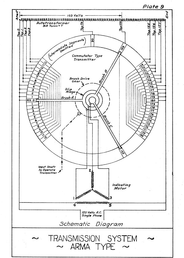
Table of Contents
Previous Chapter (2)
Next Chapter (4)
Transcribed and formatted by Thomas Wildenberg


