CHAPTER 5
GENERAL ELECTRIC SECONDARY BATTERY TYPE
FIRE CONTROL INSTALLATIONS.
1. The General Electric secondary battery type fire control
installations are installed on certain battleships, light cruis-
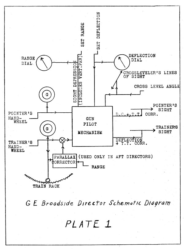
ers, and destroyers. These installations are very similar on
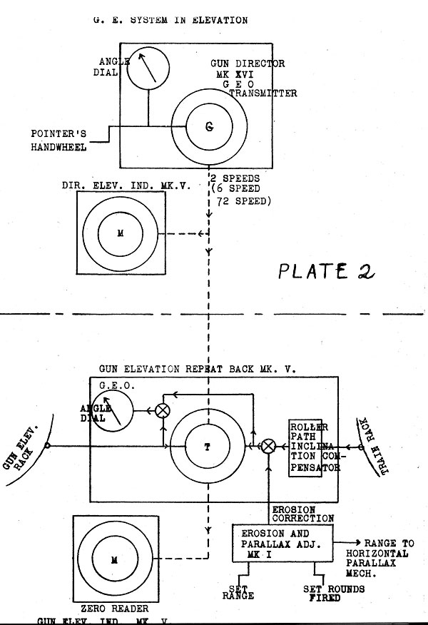
all three types of ships.
2. The system has been installed on ships as follows:
Maryland Type, Battleship Secondary Batteries:
U.S.S. Maryland, U.S.S. Colorado
West Virginia Type, Battleship Secondary Battery:
Light Cruisers, Main Batteries:
U.S.S. Cincinnati Cl 6
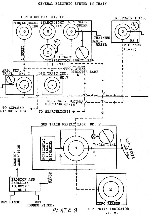
U.S.S. Raleigh Cl 7
U.S.S. Concord Cl 8
U.S.S. Trenton Cl 11
U.S.S. Maryland Cl 12
U.S.S. Memphis Cl 13
Destroyers, Main Batteries:
U.S.S. Smith Thompson DD 212
U.S.S. Barker DD 213
U.S.S. Tracy DD 214
U.S.S. Borie DD 215
U.S.S. John D. Edwards DD 216
U.S.S. Whipple DD 217
U.S.S. Sinclair DD 275
U.S.S. McCawley DD 276
U.S.S. Moody DD 277
U.S.S. Henshaw DD 278
U.S.S. Meyer DD 279
U.S.S. Doyen DD 280
3. The system on the U.S.S. Maryland will be explained in
detail. The variations of the other systems from that of the
U.S.S. Maryland will be noted afterwards.
MARYLAND SECONDARY BATTERY.
4. The G.E. Installations were developed after the World
War and first installed in ships in about 1922. They all use
--45--
the "Selsyn" transmission system. The type of installation described
in this chapter was designed for controlling the fire of broadside
batteries developing a high rate of fire. As in the Vickers broadside
installation, there is no plotting room, the
range and deflection being set on the director sights.
5. The Director (See schematic diagram, plate 1, and plate
12). The director is of the gun pilot type. In this type of
director a member known as the gun pilot is elevated and trained
as though It were on actual gun. The director is so constructed
that the proper displacement of the telescopes from the gun
pilot may be made to obtain a hit, both in elevation and train,
regardless of the cross-roll, or "trunnion tilt". The elevation
and train of the gun pilot with respect to the ship is transmitted
to the guns and these quantities
(plus or minus local corrections at the guns) are the proper amounts to elevate and
train the gun - provided the director telescope is correctly pointed.
THE ELEVATION SYSTEM. The Director.
6. Sight Depression and Director Correction. (See Plate 2) Starting
with the gun pilot and the telescopes parallel to the
reference plane, assume that a range is set on the range dial*.
This will not move the gun pilot but it will depress the pointer's
telescope below the axis-of the gun pilot by an angle equal to the
SIGHT DEPRESSION.
7. If the pointer using his handwheel now elevates his telescope
to bring it parallel to -the -reference plane, the gun pilot will be
elevated above the reference plane through the same angle. However the director
pointer is free to elevate or depress
his telescope above or below the reference plane through any
angle (director correction) in selecting the firing point.
The gun pilot is of course moved through the same angle.
8. In practice the director pointer is not concerned with
either sight depression or director correction. He merely looks through
his telescope and, with his handwheel, elevates and depresses
as necessary to insure that his crosswires will cross the
target. In doing this he
unconsciously combines sight depression and director correction to obtain GUM ELEVATION ORDER,
which is the angle between the gun pilot and the reference plane. Geared
to the pointer's handwheel is a pair of transmitters (coarse
and fine) which transmit the Gun Elevation Order to the guns.
* The range dial is graduated to include vertical parallax correction.
--46--


9. It should be
emphasized at this point that the Gun Elevation Order transmitted to the
guns simply causes, the guns to stay, parallel to the gun pilot,
regardless of the range setting or the telescope elevation (director
correction). If the range is
correctly set on the director the guns will be properly elevated for
firing when the director pointer's telescope is on the target.
In other words the director is a master sight.
10. Trunnion Tilt (Cross Roll) Compensation in Elevation. As the
ship cross-rolls the cross leveller cranks his telescope so as to keep it on
the horizon at right angles td the line of sight. The operation of
his handwheel rotates the pointer'stelescope
about the gun pilot as an axis, thereby slightly elevating or depressing it(the
pointer's telescope). This offset
causes the pointer to fire a little earlier or later in the roll.
The amount and direction of the offset
is just enough to compensate for the trunnion tilt error in elevation.
11. Roller Path Compensator. There is no
roller path compensator ±n the director. The
inclination of the roller path itself
may be adjusted in dry dock.
12. The Guns - Elevation. The Gun Elevation Order from the
director goes to the rotors of the two transformers (coarse and
fine) in the Gun Elevation Repeat Back.* The rotors of these
transformers are geared mechanically to the auxiliary elevating
rack on the gun, while the stators are positioned mechanically
by the algebraic sum of erosion correction from the Erosion and
Parallax Adjuster** and the roller path inclination compensation
from the roller path compensator in the indicator. The electrical
output of the stators is the difference between the Gun
Elevation Order and the elevation of the gun (corrected
for erosion and r.p. inclination. This
output goes to the Elevation Indicator, which contains a pair of
motors mounting dials which
indicate to the gun pointer how to elevate. A pair of mechanically
driven dials is included in the "Repeat Back". These show
the elevation of the gun (corrected for erosion and r.p. inclination).
THE TRAIN SYSTEM.
13. The Director-Deflection. (See Plates 1 and 3). If the
director's deflection is set on arbitrary zero the gun pilot is
trained on the same bearing as the director telescope (neglect
ing trunnion tilt and horizontal parallax corrections). When a
deflection is set, the director telescope is offset from the
* "Repeat Back" is a misnomer. It does not "repeat back".
** Which is kept set by the sight setter for rounds fired and range.
--47--
gun pilot. When the trainer trains
back onto the target he offsets the gun pilot from the line of sight and
thereby -applies deflection to the relative target bearing, yielding GUN TRAIN
ORDER, which is transmitted to the guns. The guns therefore follow
the gun pilot in train as well as in elevation.
14. T.T.
Compensation in Train. The
operation of the crossleveler's handwheel, acting through the gun pilot mechanism as
explained in Paragraph 10, applies a further offset of the telescope
from the gun pilot in train. This offset, as is the case
with the T.T. correction in elevation, varies with the crosslevel angle
and with the elevation of the gun pilot. If the director telescope is
kept trained on the target the gun pilot
will be continuously corrected in deflection for "trunnion tilt".
So will the GUN TRAIN ORDER.
15. Horizontal
Parallax - After Directors. The after directors each have an
eccentric h.p. mechanism, so constructed that
when the range is set the telescopes and gun pilot are offset
properly to correct for h.p. from the forward director. When
the trainer keeps "on" he automatically introduces the correction into the Gun Train Order.
16. The Guns
- Train. The Gun Train Order
is transmitted at
1 and 72 speeds to the rotors of two transformers in the Gun
Train Repeat Back* at each gun. The rotors of these transformers are
geared to the auxiliary training rack and the stators
to the parallax mechanism, which is controlled by the gun train
angle. and the range from the Erosion and Parallax Adjuster.
Thus the relative position of the rotors with respect to the
stators is gun train angle corrected for horizontal parallax
between the gun and the forward director. The electrical output of
these transformers is the difference between Gun Train Order and
Gun Train Angle (corrected for parallax). This difference is
shown by a pair of zero readers in the train indicator, thereby
enabling the gun trainer to follow.
17. Divided Fire. As the guns on each side are divided into
two groups with a group control station and director for each
group, divided fire is easily: used. The switching equipment is
such that any gun may be controlled by either director on the same side.
18. Indirect Fire. There is no provision for indirect fire.
19. Since the 5-inch guns can also be used for star shell
duty two additional transmitting instruments are provided in
each group control station. One of
these, the Independent Train
* "Repeat Back" is a misnomer. There is no repeating back.
--48--

Transmitter Mark I (mounted near the director), can- transmit an
independent train angle (i.e. independent of .the director) at 1 and 72 speeds,
through suitable switches, to the five inch gun director train bus.
The other, an Arbitrary Deflection
Transmitter Mk I (mounted on the director) has a transformer which receives
target bearing from a selsyn generator in the gun director at 1
(coarse) speed only, modifies it by an arbitrary amount of deflection and transmits
the resultant to the director train bus.
20. The switching arrangement in the group control station is such
that either the independent train transmitter can control any or
all of the 5-inch guns when assigned to star shell duty.
21. The same generator which supplies target bearing to the arbitrary
deflection transmitter can supply target bearing to the exposed
range finders and to Director Train Indicators in either control
station on the same side.
22. A separate generator in the director transmits target bearing
at 1 speed to a transformer in the director the stator of
which may be rotated by a hand crank to introduce any desired arbitrary
deflection to the train of the searchlights.
23. Searchlights may also be controlled by the independent train
transmitter but only at 1 speed. Searchlight Indicators
have only a coarse dial.
24. Only the Independent Train Transmitter can be employed to
transmit train angle to both the star shell guns and the search
lights. In this case their control is independent of the director
(useful for searching).
25. If it is desired to control the star shell gun and searchlights
from the director which controls the guns which are firing at
the target, the searchlight's must be controlled by the searchlight
train transmitter, and, the star shell guns must (if they are
to have separate deflection control from that of the
other guns) be controlled by the arbitrary deflection transmitter
at 1 speed only. Searchlights and star shell gun may be varied
independently in deflection, but only the low speed dials are used.
26. Instruments are supplied to the various F.C. stations as follows:
Group Control Stations:
1 Gun director Mk XVI
1 Arbitrary Deflection Transmitter Mk I 1
Independent Train Transmitter Mk I 1
Director Elevation Indicator Mk V 1
Director Train Indicator Mk V
--49--
Broadside 5" Guns:
1 Gun-Train Indicator Mk V
1 Gun Train Repeat Back Mk V
1 Gun Elevation Indicator Mk V
1 Gun Elevation Repeat Back Mk V
Errosion and Parallax Adjuster Mk I
Exposed Range Finders:
1 Range Finder Train Indicator Mk V
1 Range Finder Train Repeat Back Mk V
1 Range Finder Train Repeat Back Mk V Mod. 1
(For after exposed range finder only)
Searchlight Control Stations:
1 Searchlight Train Indicator Mk V
1 Searchlight Train Repeat Back Mk V
WEST VIRGINIA INSTALLATION.
27. The West Virginia secondary battery installation is a
modification of the Maryland installation. Except for the important
development indicated in paragraph 28, and the addition
of a battle order visual system, the changes are of a minor
nature. However they will be listed briefly:
(a) There is no "arbitrary deflection
transmitter". Instead the searchlight train transmitter is so connected that it can transmit both to the
searchlights and to any guns assigned to star shell duty.
(b) There is a battle order visual system, by
means of which range, deflection, and battle orders may be transmitted to the guns.
(c) There are no elevation indicators in the control stations.
28. Ball-bearing
Mounted Zero-Reading Motors. In the Mary
land, at each gun station there is a "repeat back" containing a
"transformer" which electrically receives the gun elevation (or
train) order, and mechanically receives the actual elevation (or
train) of the gun. The difference is transmitted electrically
to an adjacent selsyn "motor" which indicates to the pointer (or
trainer) how to elevate (or train). In the West Virginia the
repeat back and transformer are eliminated. Instead, the stator
of the indicating motor is mounted in ball bearings and geared
to the auxiliary elevation (train) rack. The position of the
stator then represents the elevation (train) of the gun. This
value is indicated on an "angle dial", showing the gun's angle
of elevation (or train). The position of the motor's rotor with
respect to the stator is determined by the gun elevation (train)
order received. The directions of rotation of the stator and
rotor are reversed, so that if, for example, the director is
--50--
trained to
the right the zero pointer at the gun (attached to the rotor of the motor) will be moved by
electricity to the left. Seeing this, the gun trainer instinctively
trains right the same amount, thereby rotating the stator until
it has mechanically carried the
rotor back to the zero position. In the above explanation only one
motor has been mentioned. Actually there are two: coarse
and fine. Also the mechanical input to the stators is modified by
corrections, such as horizontal parallax, erosion, etc. This
elimination of the "repeat back" transformer is a big improvement, because it
eliminates unnecessary units.
LIGHT CRUISERS.
29. The light cruiser main battery (6-inch) installations are
like the West Virginia Installation except as follows:
(a) The director has a stabilized, sight, Mark II, with
automatic firing mechanism.
(b) There is no range and deflection transmitter.
(c) The 3-inch AA guns can be controlled- in train only.
DESTROYERS.
30. The destroyer installations are
similar to the West Virginia installation,
except as follows:
(a) The director has a stabilized sight, Mark II, with
automatic firing mechanism.
(b) The battle order transmitter is attached to the director.
(c) There is not a separate target bearing transmitter in
the director. However the director transmits to the searchlights
through a transformer, by means of which an
arbitrary deflection may be applied.
31. Unlike the light cruiser
installation, there is no transmission of train to the AA guns.
--51--
Table of Contents
Previous Chapter (4)
Next Chapter (6)
Transcribed and formatted by Thomas Wildenberg


