
CHAPTER 7
RANGEKEEPER MARK I, MOD. 3
1. Intelligent operation of any rangekeeper requires a
thorough understanding of how it functions. Contrary to popular
belief, rangekeepers are not too complicated for the average per-
son to master. Given a good instruction
book, any officer can,
in a comparatively short time, thoroughly grasp the construction
and functioning of any rangekeeper. When the Mark I rangekeeper
is mastered, other and more complicated rangekeeper s can be
easily understood.
2. Before studying this chapter O.D. 1661 should be studied,
and FTP 134, Articles 500 to 517 should be read. It is assumed
that Chapter 1 of this book (PGS 5) has been thoroughly studied.
Function.
3. The primary function of the Mark I Mod. 3 rangekeeper is:
TO
GENERATE CONTINUOUSLY ADVANCE RANGE. DEFLECTION,
AND (FOR USE IN INDIRECT FIRE) TARGET BEARING.
From these
quantities, other instruments obtain and transmit to the turrets:
4. If the Mark I Mod. 3 rangekeeper were perfect, and if
all of the data introduced were correct, the rangekeeper would continuously
generate the hitting advance range, deflection and target bearing.
Since neither of these conditions can
be counted upon the rangekeeper is designed to facilitate the correction
of errors in the data, and the application of ballistic corrections.
The general scheme by which the
rangekeeper is made to accomplish its mission is indicated in the following steps:
(a) Receive initial data (known or estimated) as to own
ship's motion, target's relative position, and target's motion.
(b) From this data compute the rates at which
the range and bearing should be changing.
(c) As time passes, integrate the changes in
range and bearing due to the rates obtained under (b) and add the total changes
to the Initial range and bearing.
(d) Provide suitable means for comparing the values of present
range and bearing thus generated with the range and bearing which is
constantly being observed. This comparison assists the operator
in adjusting the doubtful inputs.
(e) Compute certain ballistic corrections.
--74--
(f) Provide means for introducing by hand any desired
ballistic corrections.
(g) Generate the resulting advance range deflection, and
target bearing.
5. The initial data introduced is:
(a) Own ship's course and speed. These are assumed to be accurate.
(b) Target bearing (Relative) . This is easily and continuously observed,
and assumed to be accurate.
(c) Present Range. This is estimated or measured by rangefinders,
and may be greatly in error, depending upon the visibility, range, etc.
(d) Targets' course and speed. These are estimated and may
be greatly in error, depending upon the visibility, etc. Target's course
may be given as a compass course, or as Target
Angle, which really defines the target's course with respect to
the line of fire.
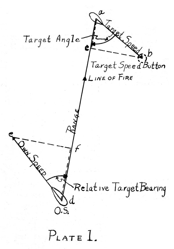
6. Plate 1 is a graphical representation of the above data.
Own ship's course and speed are represented by the direction and
length of d e. Relative Target Bearing (which incidentally
defines own ship's course with respect to the line of fire) is e d
a. Range is d a. Target's course and speed are
represented by the direction and length of a b. Target Angle
(which really defines target's course with respect to the line of fire) is bad.
Computation of Rates.
7. Referring
again to Plate 1, it will be seen that own
ship's motion d e may be resolved into two components: d f in
the line of fire and f e across the line of fire. Similarly,
the target's vector may be resolved into a c in the line of
fire and c b across the line of fire, a c plus d f is the
speed at which the two ships are approaching each other, and is
called the RANGE RATE. c b plus f e equals the relative speed
at which the ships are moving across the line of fire and may be
called the LINEAR BEARING RATE. Note that these two speeds or
rates are
independent of the range. They may
be positive or negative, and in obtaining them the correct signs must be used.
In this case illustrated in Plate 1 the range rate is decreasing or negative,
but the linear bearing rate, since the line of fire is being swung to the
right, is positive.
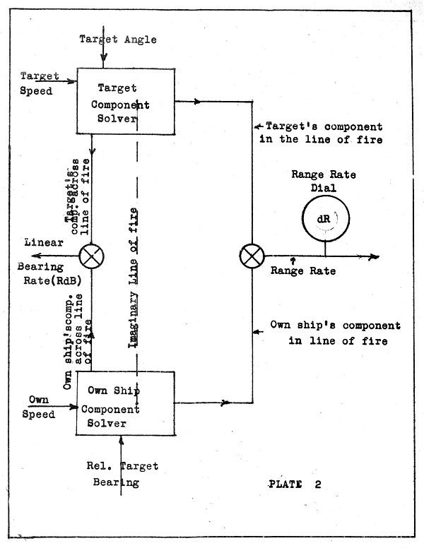
8. The
rangekeeper mechanically computes these two rates as
indicated schematically in Plate 2. The Own Ship and Target
component solvers resolve their vectors into components in and
--75--
across the line of fire. One differential
adds algebraically the two components in the line of fire to obtain
RANGE RATE. Another differential adds algebraically the two components across
the line of fire to obtain the LINEAR BEARING RATE (or "Deflection
Rate"). These rates may be
expressed in knots, yards per minute, or similar units. The Range Rate
is indicated on a dial
in knots, but there is no bearing rate dial.
9. The Range
Rate (dR) may be used directly to change the range. Since bearing is
measured in angular units (degrees) it is
necessary to have the angular rate at which the bearing is
changing. This depends not only
upon the relative speed across the line of fire but also upon the
range. In fact the Angular Bearing Rate
(usually called simply the "bearing rate") is equal (in radians per
minute) to the Linear Bearing Rate (in yards per minute) divided by the
Range.(in yards). It may be
converted into degrees per minute by a conversion factor.
10. The above
relationship may be expressed as follows, omitting the conversion factor:
Linear Bearing Rate = Angular Bearing Rate x Range or using
convenient symbols:
RdB = dB × R
or
dB = RdB/R
11. The rangekeeper performs the operation indicated in the
last equation. The Linear Bearing
Rate (RdB) goes to a multiplier (which can of course divide) where it is
divided by the Range (R) giving as its output the (angular) Bearing Rate . (dB)
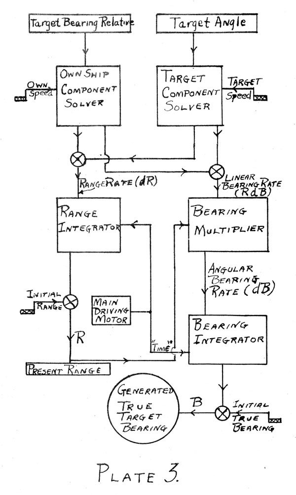
Integrating the Changes in Range and Bearing. (See Plate 5)
12. The Range Rate (dR) obtained from the component solvers
is used as an input to the range integrator. The other input is
"time" from the constant speed driving motor. The out-put of the integrator is a
change of range which is added continuously to the existing range to give the
generated present range.
13. In a similar manner the (angular) Bearing Rate (dB) is
put into the Bearing integrator and the change of bearing obtained as the output. This change
of bearing is added to the
initial true bearing and thus produces generated true bearing.
Generated relative bearing is easily obtained by subtracting own
true course.
Comparing
Generated Values with Observed Values of Range and Bearing.
14. The graphic plotter furnishes the best method of comparing the value of present
range thus generated with the observed
--76--
(range finder) range. It is mounted at the top of
the range-keeper. A sheet of paper
is moved steadily by the rangekeeper, as time passes. A pencil automatically
traces the generated present range. The operator of the graphic
plotter, who wears the telephone to the rangefinders, plots each range as
it is received, and fairs the mean rangefinder line. If the set up is correct,
and if the rangefinder readings
are excellent, the mean rangefinder line will coincide with the (generated)
present range line. The slopes of
the lines depend upon the rates at which the respective ranges are changing.
If the lines are parallel, the rates are equal. If not, then the
rangekeeper range rate (dR) is in error - assuming that the rangefinder range
rate is correct. If dR is
incorrect, then the settings of target's course and speed (either or both) are
in error.
15. There are other ways of detecting errors in dR. The Mark
II plotting board, though less convenient, can be used in the
same manner. The HORIZONTAL WIRE is also, available, although
seldom used. It is so controlled by the rangekeeper that when
a new range or range ballistic correction is cranked into the rangekeeper it will
move up if the range is increased or down if it is
decreased. The wire is normally
over the speed button which shows the target's course and speed settings.
The direction in which the wire
moves indicates the corresponding direction in which the settings should
be corrected. The details of the
horizontal wire mechanism, being unimportant, will not be described.
16. Comparison of the observed relative target bearing with
the generated relative target bearing is shown by the VERTICAL
WIRE. The Vertical Wire is driven
from a differential whose inputs are observed target Bearing
(Relative) and generated Target
Bearing (Relative). If they differ, the vertical wire will move
off the target Speed button in the direction in which the button
should be moved to correct the target's course and or speed settings.
17. If the target's course and speed settings are correct,
both the range rate (dR) and the bearing rate (dB) must be correct.
The rangekeeper operator, by
trial and error, adjusts the
target's course and speed settings until these two conditions
are met. That is, until the
graphic plotter lines show him that
the range rate is correct and the vertical wire shows him that
the bearing rate is correct. However, in practice, the rangekeeper
operator depends largely on the spotter's estimate of the
target's course, or target angle. Later rangekeepers employ a
vernier in place of the vertical wire, but this does not change
the method of operation.
--77--
Computing Certain Ballistic Corrections.
18. Rangekeepers vary greatly in the corrections which they
automatically compute and apply. In general, some of the ballistic corrections
are automatically applied by the rangekeeper,
while others must be computed separately and inserted like spots.
The corrections computed by the Mark I Mod. 3 rangekeeper will
be described.
Corrections in Range.
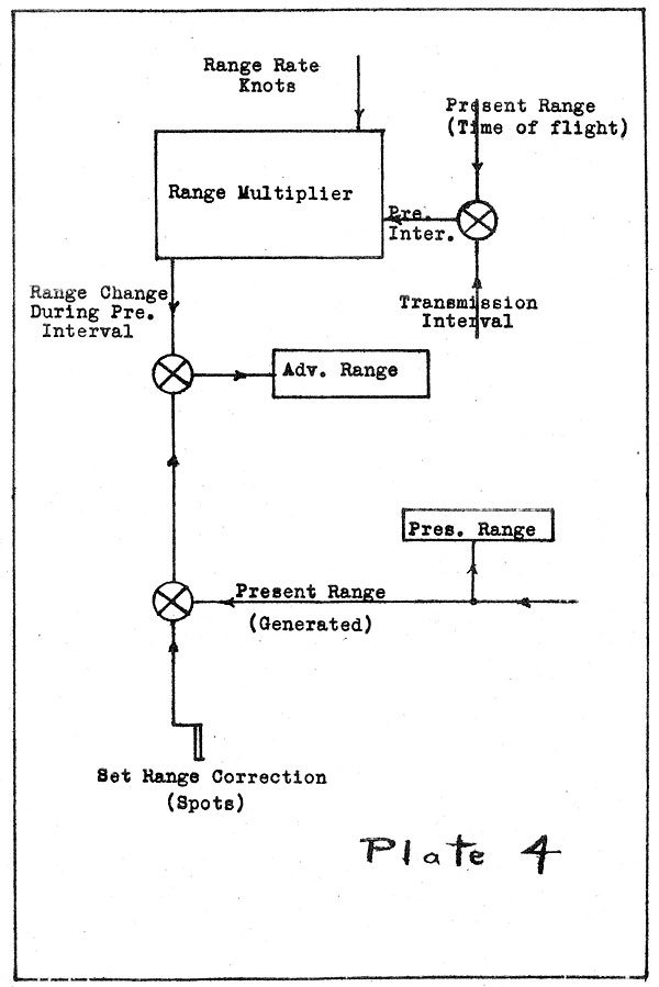
19. Own Ship's and Target's Motions. There is a small time
delay in getting Advance Range from Rangekeeper finally applied
(as gun elevation) to the guns. This is called the transmission interval. There is also a
much longer time from the firing
of the gun until the projectile arrives at the target (Time of
Flight) . During the total of these two intervals (called the
"prediction interval") the target may move several hundred yards,
and motion of the gun may have a similar effect. The Range correction
for the motion of the gun and target is computed by the
Rangekeeper and applied continuously to Present Range, thus giving
(after the input from the shot crank has been added) Advance
Range. This ballistic is computed in the Rangekeeper-as follows:
The time of flight is assumed to be directly proportional to the
Present Range. Although this introduces an error, the error is
small and the assumption makes it possible to avoid using a cam,
thus simplifying the machine. The shafting from Present Range
to the corrector simply has the proper gear ratio, thereby introducing time of
flight. The transmission
interval (set by hand) is added to the time of flight by a differential
before it reaches the corrector. The corrector itself is merely a multiplier which receives the
"prediction interval" as just described, and the Range Rate
(dR), multiplies them, and puts out the predicted change of range.
The generation of Advance Range is as indicated by Plate 4.
20. Wind. There is no corrector for the true wind nor for
the wind due to gun's motion. Consequently the wind ballistic
must be computed separately, using apparent wind.
Deflection.
21. Own and Target Motions and Wind. The
Rangekeeper also computes the deflection correction due to motion of gun and
target, adds in drift, and indicates the total on the deflection
dial. This is done by the Bearing
Multiplier as shown in Plate 5. The deflection correction due to wind
must be computed separately using apparent
wind," and applied like a spot. The bearing multiplier has two functions.
One is to compute the deflection due to own ship's motion, target's motion, and drift.
This is done with the aid of the drift cam, as indicated. The
--78--
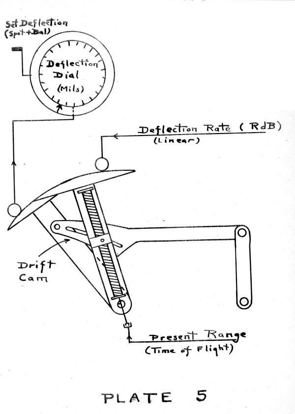
RdB input
represents the relative movement across the line of fire of own ship and
target. This does not correct for
either true wind or wind due to gun's motion, so that the correction for apparent
wind must be computed and applied like a spot.
Application of Ballistic Corrections.
22. Other corrections must be computed and introduced like
spots. Due to the approximations, especially in range, it is
best, if time permits, to compute the entire ballistic corrections
(range and deflection) and "force" them on the rangekeeper
using the spot cranks. Whenever
the ship changes course the apparent wind changes, which will cause errors unless a corrected
ballistic is applied. The later rangekeepers are much improved;
most of them need not be corrected for changes in course. Also
more corrections are handled by the rangekeeper.
Generation of Relative Target Bearing.
23. The Bearing Integrator was discussed in Par. 13. The output of the integrator
is generated true bearing. For use in in
direct fire and in making comparisons, the generated relative
bearing is required. Target Course Relative to Own Course and
Target Angle are also required for the face dials and component
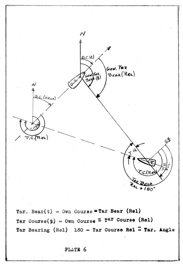
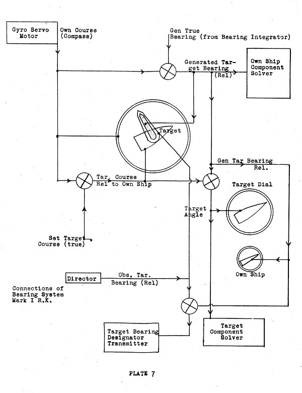
solver. The relationships between the various angle is shown
in plate 6. The methods of obtaining them,
and the connections between the various angle dials is shown in Plate 7.
Summary.
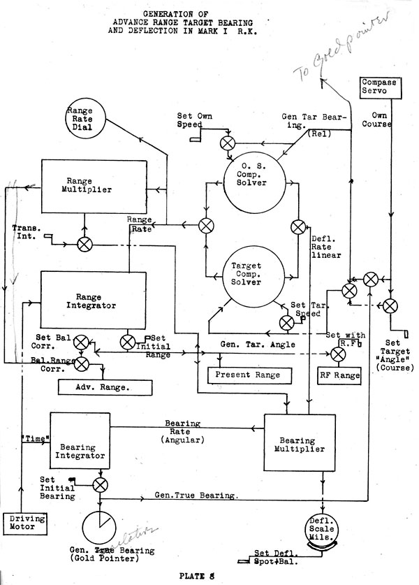
24. The various units in the Rangekeeper have been taken up
in detail. It remains to place them in the Rangekeeper and
show their relation to each other. This is shown schematically
in Plate 8. No attempt has been made to show details such as
the. connections for the horizontal and vertical wires and the
graphic plotter. Later modifications also have servo motors and
selsyns for transmitting some of the outputs electrically. The
method of operation and essential mechanisms are shown so that
all inputs may be traced thru the system to obtain the final outputs.
--79--
Table of Contents
Previous Chapter (6)
Next Chapter (8)
Transcribed and formatted by Thomas Wildenberg


