CHAPTER 8
SPERRY - FORD TYPE OF MAIN BATTERY DIRECTOR
FIRING INSTALLATION.
| U.S.S. Wyoming |
6 |
2"/50 |
| U.S.S. Arkansas |
12 |
2"/50 |
| U.S.S. California |
12 |
14"/50 |
| U.S.S. Tennessee |
12 |
4"/50 |
1.
Although this system is obsolescent, its simplicity makes it excellent as- an.
introduction to main battery fire control installations. At this point it
is timely to caution the student that there has been a gradual change in fire
control nomenclature. For
example, the instrument now called "Gun Train Indicator" in all
installations was called "Single Target Turret Indicator" in the
Sperry "installation, and what is now called "Gun Order" was
called "Corrected Target Bearing".
2. The Sperry-Ford System of Main Battery
Fire Control was developed piecemeal in our Navy, and comprises some apparatus that
was originally designed when director fire first made its appearance
(1913-15) and some that resulted from subsequent experience. Various parts of this
system were designed by personnel
of the Bureau of Ordnance, by the Ford Instrument Co., and by
the Sperry Gyroscope Co., and the system as a whole is sometimes
referred to as the "Bureau-Ford-Sperry System", although it is
commonly known as the "Sperry System". The elevation system,
which comprises apparatus of Bureau and Ford Design, is also referred
to as the "United States Navy type" of director firing
installations. All apparatus of the train system is of Sperry design.
3. The Elevation System, using Ford instruments, employs the
Ford Transmission System1 which is self-synchronous but has a
limited number of steps. The Train System is Step-by-Step, and
is not-self-synchronous.
GUN ELEVATION SYSTEM - FORD INSTRUMENT CO. GEAR
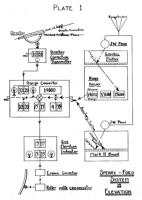
4. The accompanying diagram (Plate 1) illustrates the instruments involved
in the gun elevation system, the lines with arrows indicating the paths
of the two elements affecting gun elevation - namely:
(a) Advance Range.
(b) Director Correction.
1Not to be confused with the later Ford "DCS" system.
--80--

5. Advance Range (in yards) is obtained from the range keeper
Advance Range Dial (or, from the Plotting Board). This range is
set by handcrank into the Range Converter, where it is converted
to the corresponding elevation in minutes (or "eight depression"),
to be combined with the Director Correction of the Firing Director.
6. The-mechanism for converting Gun Range to "Range in Minutes"
sight depression) consists of a hand crank geared to a drum. The drum is graduated for
range in yards in such, a way that when the range is set on the
drum, the drum; is thereby turned angularly through the corresponding "range in
minutes" given in the range table. Actually the drum, has two sets of
graduations, one for "full charge" and the other for "reduced charge".
7. Director Correction is transmitted from the Firing Director
by the Director Correction Transmitter to the Range Converter,
where it registers in the upper left hand window (Plate 1).
Here by mean of a hand crank, the Director Correction is transferred1
by the Converter Operator to the corresponding lower
left hand dial of the Converter, which operation combines this
Director Correction with the Sight Depression and indicates the
resultant Gun Elevation Order.
8. The Gun Elevation Transmitter (located in
the Range Converter) transmits automatically the above
resultant Gun Elevation Order to the Gun Elevation
Indicators at the Gun Stations.
The Gun Elevation Indicators are controlled from the switch
board in the Plotting Room, allowing each Gun Elevation Indicator
to be throvm in circuit with either Gun Elevation Transmit
ter. Thus either Gun Elevation
Transmitter can control the elevation of all turrets, or, for divided fire, each group of
turrets may be controlled separately.
9. Gun Elevation Indicators receive mechanically from the
auxiliary gun elevation rack the angle of elevation of the gun.
Actual Gun Elevation is corrected for Roller Path Inclination
and, on later mounts, it may be corrected for erosion of the guns.
Thus, by matching pointers in the Gun Elevation Indicator, the
guns can be laid to the desired angle of elevation, i.e.: GUN
ELEVATION ORDER + EROSION CORRECTION + ROLLER PATH CORRECTION.
1The Range Converter has
included in its mechanism a "follow the pointer" system to enable the
Operator to keep the proper Director Correction set at all times without
actually reading the Director Correction.
--81--
THE SYSTEM IN TRAIN - SPERRY GEAR.
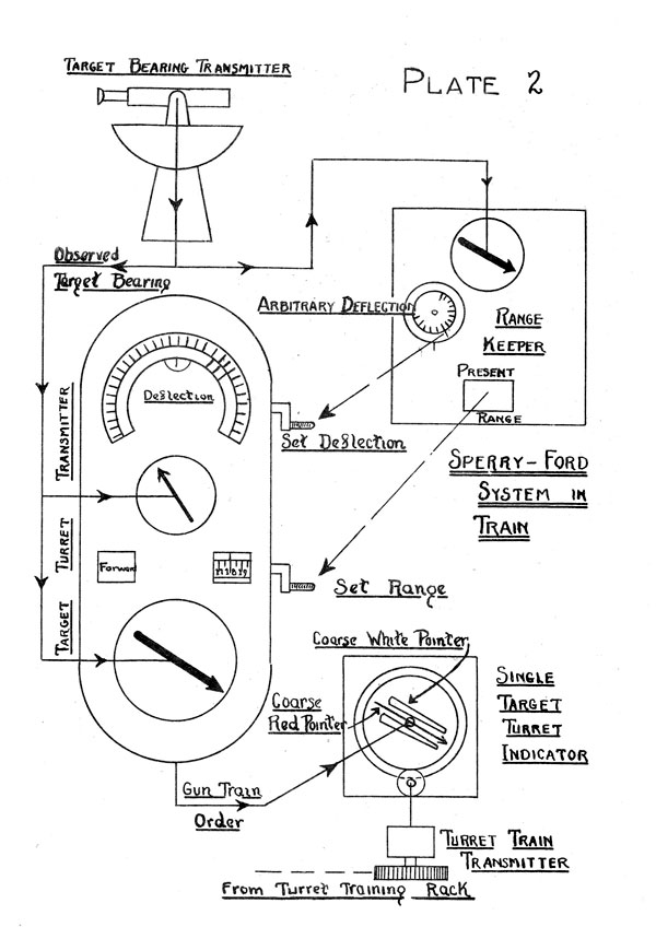
10. The accompanying diagram (Plate 2)
illustrates the instruments involved in the Gun-train system.
Lines with arrows indicate the path of the bearing signal from the Target Bearing
Transmitter to the indicator at the turret trainer's station.
11. The Target Bearing is observed by the Target Bearing Trans
mitters any of which can transmit this relative bearing to a
Target Turret Transmitter in Plot, where it registers on a pair
of dials as observed Target Bearing. There are two Target
Turtet Transmitters (T.T.T.s)in the Plotting Room, one for each
group of Turrets. In the Target Turret Transmitter the setting
of the Deflection and of the Present Range (from the Range Keep
er) apply to the observed bearing a correction which not only
introduces the Deflection but also compensates for Convergence.
(i.e., Horizontal Parallax).1
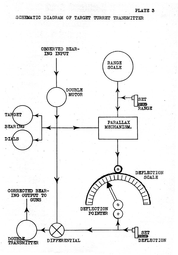
12. Operation of the Target Turret
Transmitter. (See Plate 3).
Observed Target Bearing from the Target Bearing Transmitter enters
the instrument and registers on the two (coarse and fine)
bearing dials, at the same time being introduced into a parallax
mechanism, whose other input is the range as set in the instrument. The Range is taken from the
"Present Range Dial" of the
Rangekeeper and set by handcrank. The output of the parallax
mechanism moves the Deflection scale of the instrument, so that
when the Operator sets the Deflection pointer by hand he applies
the combined correction for horizontal parallax and deflection,
through a differential, to the Observed Target Bearing. The
output of this differential is "Corrected Target Bearing" or
Gun Train Order.
13. "Target Turret Indicators", (i.e., Train Indicators). The
'Corrected Target Bearing" (Gun Train Order) is transmitted by transmitters
in the Target Turret Transmitter to the Target Turret Indicator's
in the Turrets. The Train of
the Turret is transmitted by the Turret Train Transmitter (located
near the training rack of the turret) and registers on the dials of the Target
Turret Indicators. By proper
matching of pointers the turret will now be trained to the firing bearing.
GENERAL FEATURES.
14. Control Instruments. The Sperry-Ford System affords control
from three stations in Train; namely:
1Each Group of Turrets is converged on
the Target. Therefore the Target
Turret Transmitters are not interchangeable.
--82--


-
Target Bearing Transmitter #1 in Foretop.
-
Target Bearing Transmitter #2 in Main Top.
-
Target Bearing Transmitter #3 in Fire Control Tower.
and six stations in Elevation:
-
Director #1 in Foretop.
-
Director #2 in Maintop.
-
Director #3 in Fire Control Tower.
-
Director #4 in Forward High Turret.
-
Director #5 in After High Turret.
-
Director #6 (Stable Zenith) in Plot.
15. In Plot there are also two Rangekeepers, two combined range
converters and transmitters, two target turret transmitters, and
certain auxiliary instruments.
16. Divided Fire. The Sperry-Ford System is very flexible
in Elevation, it being possible to use any one of the five directors
in conjunction with either Range Converter and Gun Elevation
Transmitter for controlling part of the battery, and any other
director with the otter Range Converter and Gun Elevation Transmitter
for the remainder of the battery. In Train, however, due
to the non-interchangeability of the Target Turret Transmitters,
the battery can only be divided into two groups (forward group
and after group), though any one of the three Target Bearing
Transmitters can control either or both groups. Consequently,
Divided Fire for the Sperry-Ford System consists of:
Group 1 - Forward Turrets controlled by Director #1, #3 or #4,
T.B.T. #1 or ,#3, and the "forward" group" of
plot, consisting of the forward rangekeeper, converter, and T.T.T.
Group 2 - After Turrets controlled by Director #2, #3 or
#5. T.B.T. #2 or #3, and the "after group" of plot, consisting of the
after rangekeeper, converter, and T.T.T.
17. Indirect Fire. Indirect Fire may be carried out with this
system using the Stable Zenith Instrument (Director, Mark IX)1
mounted in Plot as the Firing Director, and the Target Designator
System for controlling in train. A Target Designator is
mounted on each Target Bearing Transmitter. It consists of a
galvanometer with a needle1 which indicates "train right",
"train left", or "on". The
needle may be controlled by either Rangekeeper in plot. If the Rangekeeper
is properly set up, and the
director trainer keeps his designator "on", his telescope will
stay pointed at the target. In
this way a rangekeeper may control the battery in train, if the target is obscured.
1The Stable Zenith was not developed by Sperry-Ford.
--83--
Table of Contents
Previous Chapter (7)
Next Chapter (9)
Transcribed and formatted by Thomas Wildenberg


