CHAPTER 9
G.B. MAIN BATTERY FIRE CONTROL SYSTEM (U.S.S.MARYLAND)
1. The
General Electric Company developed this fire control
installation. It was installed in
the Maryland and Colorado in about
1922. Later, in a modified form, it was installed in the West Virginia.
It uses the "Selsyn" transmission system.
THE ELEVATION SYSTEM.
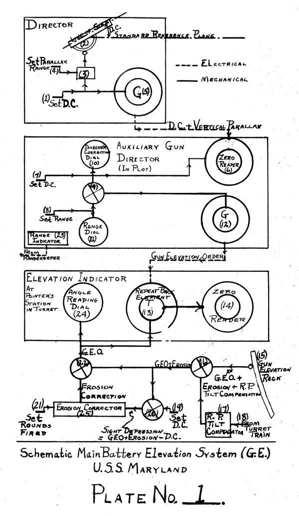
2. See Plate No. 1, Schematic Main Battery Elevation Sys
tem. The numbers in the text below
refer to this plate.
3. Any director of the system can control in elevation. Di
rectors are in the following stations:
Fore top
Maintop
Fire control Tower
Turret II
Turret III
Plotting Room (Stable Zenith)
4. One director is designated controlling director. The
pointer has a director correction handwheel (1) by which he adjusts
his sight (2) to the suitable Director Correction (D.C.)
for the roll. A mechanism (3) on which the parallax range is
set by handle (4) automatically corrects the Director Correction
for Vertical Parallax (V.P.). The resultant of director
correction and vertical parallax is transmitted by generator (5)
electrically to the director correction bus for distribution.
From this bus the D.C. goes to a zero reader (6) on one of the
auxiliary gun directors in plot.
5. This zero reader is kept matched by setting the director
correction manually by handle (7). In addition to matching the
zero reader, the movement of handle (7) also indicates director
correction on the Director Correction Dial (10) end also introduces
director correction into differential (9). Advance range
is received electrically from the rangekeeper and is indicated
on the Range Indicator (23). By moving handle (8) range dial
(11) is made to agree with the indicated range. The range, converted
into minutes by the mechanism, is introduced into the
differential (9). The differential (9) combines the advanced
range and the director correction. The output is Gun Elevation
Order (G.E.O.). This goes to
generator (12) which transmits
G.E.O. electrically to transformers (13) on the Elevation Indicators
at all pointers' stations in all turrets.
--84--

6. Transformer (13), called a "repeat back element", is a,
combined electrical and mechanical differential. Here the "ex
isting gun elevation" (Note: Tnen the,guns are properly laid
Existing Gun Elevation Equals Gun Elevation Order plus Roller
Path Compensation Erosion) corrected for the compensation for
erosion and roller path compensation is deducted from the Gun
Elevation Order electrically received and the resultant is
indicated on a zero reader (14). The zero reader indicates the
amount and direction the gun must be elevated or depressed to
make "existing gun elevation" agree with G.E.O. received.
7. As stated above (assuming the gun is properly laid), "existing gun
elevation" is the algebraic sum of the Gun Elevation
Order, roller path compensation and erosion. Elevation rack
(15) transmits gun elevation to differential (16). The roller
path tilt compensator (17), actuated from the turret train rack
(18), introduces the roller path compensation for the angle of
train into differential (16). This differential removes the
roller path compensation from the gun elevation leaving G.E.O.
plus Erosion. This component goes to differentials (20) and
(22). At differential (20) director correction is introduced
by handle (19) and the differential removes B.C. from G.E.O.
leaving actual sight depression which goes to the erosion corrector (25). Rounds fired are set
by handle (21). These two
introduced values in the erosion corrector determine the erosion
correction which goes to differential (22) where the erosion is
removed from G.E.O. plus Erosion. G.E.O. alone remains. This
goes to angle reading dial (24) and to the transformer (13).
If the gun is elevated to the proper elevation the G.E.O. thus received mechanically is
the same as the G.E.O. received electrically from the auxiliary gun
director. In that case, the zero reader (14) will be matched.
THE SYSTEM IN TRAIN.
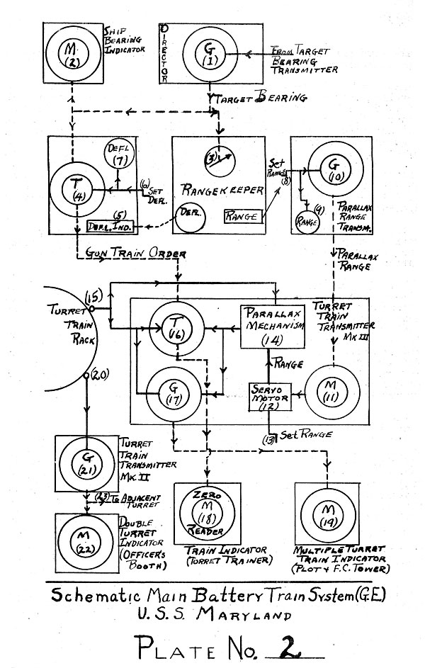
8. See Plate No. 2, Schematic Main Battery Train System.
The Numbers in the text beloxv refer to this plate.
9. There are five controls for director fire train:
Foretop director Maintop
director Firecontrol Tower
Director Plot - Rangekeeper
No. 1 Plot - Rangekeeper
No. 2
Rangekeepers are used in case the target is obscured from the director (indirect fire).
10. The trainer of the controlling director trains his telescope on the
target. The training wheel and gearing drive a
--85--
generator (1) which transmits relative target bearing to the director train bus.
11. Directors in the foretop and maintop have horizontal parallax
mechanisms attached. Since director in the foretop is so
close to the reference point in train, i.e., the firecontrol tower, its
horizontal parallax mechanism is locked on zero. The mechanism functions
on the maintop director. It introduces an angular displacement
between the telescope and the training element, this angle being
equivalent to the parallax angle to the fire control tower for any definite
range and bearing of the target. Thus the director in the maintop,
when trained on the target, transmits
the bearing the telescope would have if it were located at the point of
reference. The horizontal parallax
mechanism is not shown in the schematic diagram.
12. The target bearing from the director train bus goes to various ship bearing indicators
(2), to the auxiliary gun director transformer (4) and to the rangekeeper
(3). Both of the latter instruments are in the plotting room.
13. The rangekeeper generates the deflection which is transmitted electrically
to the deflection indicator (5) on the auxiliary gun director. The operator
keeps this deflection set by means of handwheel (6). The
deflection set is registered on dial (7). By setting deflection by
handwheel (6) the deflection
is introduced mechanically into transformer (4) which also re
ceives electrically the relative target bearing, as stated above.
The transformer (4) adds together algebraically the deflection
and relative target bearing as received to produce "corrected
target bearing" or Gun Train Order which is transmitted to the
Turret Train Transmitters Mark III at the turret racks.
14. Also in plot is a Parallax Range Transmitter located
near the rangekeeper. The operator
of the Parallax Range Transmitter reads the range from the rangekeeper and sets it by
andle (8). This set range is indicated on dial (9) and is also
entered into the generator (10) of the Parallax Range Transmitter.
This generator transmits the
parallax range to the parallax range receiver element motor (11)
in the Turret Train Transmitters Mark III. This motor
actuates a servo motor (12) which
can also be actuated by hand crank (15). This servo motor ad
justs the parallax mechanism (14). The parallax mechanism consists
of a system of cranks and levers which rotates the staters
of the train repeat back transformer (16) and of the train
transmitter generator (17) by the amount of the parallax angle
between the turret and the reference point.
15. As stated above, Gun Train Order comes from the auxiliary
gun director to the train repeat back transformer (16). Actual
train of the turret is introduced mechanically by means of pinion
--86--

(15) to the repeat back element (16). The
"repeat back" element deducts the actual train of the turret (as
modified by the parallax correction) from the gun train order and indicates the
difference on the zero reader (18) of the train indicator at the turret
trainer's station. When the zero
readers are matched the turret is trained on the proper bearing.
16. The actual
train of the turret (15) is also introduced
into the train transmitter generator (17). This generator generates
actual train of the turret compensated for the parallax
(which is applied by mechanically offsetting the stator) and
transmits this value (which equals gun train order if the turret
is matched) to the multiple turret indicators in plot and the
fire control tower.
17. Actual turret train is also transmitted mechanically from
pinion (20) on the train rack to the generator (21) of the turret
train transmitter Hark II. This generator transmits actual
train of the turret to motors (22) and (23) of the Double Turret
Train Indicators in the Officers' Booths of own and adjacent turrets.
Divided Fire.
18. In elevation the following directors may control so as to
transmit the "director correction"
| For |
forward group
Foretop Director
Firecontrol Tower Director
Turret 2 Director |
| For |
After group
Maintop Director
Turret 3 Director. |
19. In train, the following may control so as to transmit
relative target bearing:
| Forward Group |
| |
Foretop director |
| |
Firecontrol director |
| |
Rangekeeper #1 with its target bearing relay transmitter Mark V Mod. 1
(Used in case Turret 2 director controls in elevation) |
| After Group |
| |
Maintop director |
| |
Rangekeeper #2 with its target bearing relay transmitter Mark V Mod. 1
(Used in case Turret 3 Director controls in elevation). |
--87--
20. The auxiliary gun director #1 and parallax range transmitter #1 in plot are used
with the forward group; auxiliary gun director #2 and parallax range
transmitter #2 are used with the after group.
Indirect Fire.
21. In case
aloft directors are disabled the director correction (B.C.)
is supplied to the auxiliary director by the gun director Mark XIII
located in the plotting room. The director
consists essentially of (a) an element stabilized by the action
of two opposed gyroscopes, carrying an artificial horizon
against which D.C. may be observed; (b) a target bearing mechanism
carrying a telescope arm and director correction mechanism
which is constantly trained on the bearing of the target so that
the telescope will observe the director correction angle on the
proper bearing; (c) a telescope which may be given any director
correction angle so that when telescope crosslines pass the
artificial horizon due to the ship's roll, the observer can
fire; (d) Selsyn generators to transmit the director correction
to the auxiliary gun director.
22. For relative
target bearing in case of indirect fire one
of the rangekeepers and its target bearing relay transmitter
Mark V Mod. 1 is put in control. The rangekeeper generates the
compass bearing of the target and sends it to the target bearing
relay transmitter which also receives "compass" electrically.
The target bearing relay transmitter subtracts "compass" from
the generated compass bearing of the target and electrically
transmits the resultant, namely generated relative target bearing, to the director train bus.
Special Motes.
Switching.
23. In the Maryland - Colorado the switching arrangements
are such that if director 1, 2 or 3 (Foretop, maintop end fire
control tower) is used at all it must control both in train and
elevation (A rangekeeper may control in train while a director
controls in elevation). Later installations have more flexible
switching arrangements.
Multiple Turret Train Indicators (in Plotting Room and Fire Control Tower).
24. On the Maryland - Colorado there are a pair of dials for
each turret, one coarse and the other fine. The coarse dial has
a turret painted on it and indicates the approximate train of
the turret. The fine dial has a pointer indicating accurately
--88--
the turret train corrected for parallax. In later installations
the FINE DIALS are zero readers and show the turret' s error in matching; with
the received Gun Train Order.
25. The West Virginia installation is similar to the Maryland - Colorado installation
as 'described above. Instruments
in the West Virginia installation carry out the same functions as in
Maryland. However the instruments
have some refinements. over the Maryland type and the system is more flexible
on the West Virginia due to the better switching provisions.
--89--
Table of Contents
Previous Chapter (8)
Next Chapter (10)
Transcribed and formatted by Thomas Wildenberg


