Chapter V
Amphibian Vehicles

Section 1. General Description of LVTs.
Section 2. Employment of LVTs.
Section 3. Control of LVTs.
Section 4. Transferring from LCV(P)s to LVTs.
Section 5. Training--General.
Section 6. Operations of LVTs.
Section 7. Transporting LVTs.
Section 8. Suggested Method for Embarking LVTs in LSTs.
Section 9. Embarking LVTs in LSMs.
Section 10. Loading LVTs.
Section 11. Communications.
Section 12. Supply, Repairs and Servicing.
Section 13. General Description of DUKWs.
Section 14. Employment of DUKWs.
Section 15. DUKW Control in Large Operations.
Section 16. Operating With LSTs.
Section 17. Operating With LSDs, LSVs, LSMs, etc.
Section 18. Mooring at Shipside.
Section 19. Cargo Handling.
Section 20. Combat Shipment on AP or AK.
Section 21. Operational Estimates.
Section 22. Maintenance and Servicing.
Section 23. DUKW Training.

Section 1. General Description of LVTs

  1. The demands of amphibious warfare have necessitated the development of several types of amphibian vehicles capable of meeting the rigid requirements of combat. Amphibian Tractors, Amphibian Tanks and Amphibian trucks have been tested and tried in battle and are now an integral part of amphibious operations. Although they have been successfully used in combat, no standard doctrine has been established covering the use of LVTs and DUKWs in all phases of landing operations. It is the purpose of this chapter to set forth means and methods of handling and employing these types of vehicles in order to disseminate information to all amphibious forces.

  2. TYPES: At present the following types of LVTs are in use:

    1. The LVT(2) and LVT(4), commonly called the amphibian tractor, cargo.

    2. The LVT(A)(1) and LVT(A)(4), commonly known as the amphibian tank.

    3. The LVT(3) (cargo type) now under construction, will be available in 1945.

»V-1«

  1. CHARACTERISTICS -- GENERAL:

    1. The LVT(2), LVT(3) and LVT(4) are slow, lightly armored or unarmored amphibian tractors designed to transport troops and cargo from ship to shore, or shore to shore. Troops and cargo must be loaded and unloaded over the sides of the LVT(2). The LVT(3) and LVT(4) have a stern ramp, which, when lowered, allows easier unloading of troops and cargo and permits 1/4-ton trucks, guns and other wheeled equipment to load and unload over the ramp.

    2. The LVT(A)(1) and LVT(A)(4) are slow, lightly armored amphibian tanks designed to give support in approaching a beach and during the initial push inland until tanks are landed and available.

    3. Detail characteristics are given in Chapter VIII. [???? S/b Chapter VI? ????]

  2. CAPABILITIES:

    1. LVTs can negotiate reefs and shallow water areas the naval landing craft cannot cross.

    2. LVTs can operate and maintain direction in reasonably rough water and can operate through surf up to ten feet.

    3. When waterborne, LVTs have a low silhouette and are then least vulnerable to fire. While waterborne, the LVT(A)(1) or LVT(A)(4) can deliver area fire with its 37mm or 75mm gun respectively. In order to deliver accurate fire on shore targets the amphibian tank must be stationary on a reef, or approach on smooth, firm footing.

    4. LVTs can negotiate many types of terrain such as sand, coral, light woods, and, if sufficient flotation or traction exists, swamps, including some mangrove. They are capable of climbing steep slopes, depending upon traction afforded. They can cross barbed wire both on land and in the water.

    5. The LVT can proceed inland to discharge troops and cargo under cover, but distance inland should be held to a minimum.

    6. Armored LVTs can withstand glancing small arms fire and shell fragments.

  3. LIMITATIONS:

    1. The LVT is a slow, heavy vehicle with limited maneuverability and a high rate of gas consumption. It has neither the speed nor the life of a boat or truck, and normally requires a major overhaul after 200 hours of operation. LVTs have operated continuously for over 300 hours without overhaul.

»V-2«

    1. The maintenance requirements of these vehicles are much greater than other fighting equipment and considerable time must be allowed for servicing due to the adverse conditions under which they must operate. Salt water corrosion and minor damages must be corrected at the earliest possible time before they develop and render the vehicle useless. Many hours each day must be devoted to 1st echelon maintenance if they are to remain in operation.

    2. Limited visibility from the LVT makes control of units by visual means difficult.

    3. Coral heads and large rocks will damage the hull or strand an LVT.

    4. Insufficient traction, such as deep mud, will cause the LVT to belly-up.

    5. Unnecessary maneuvering in the water will cause heat and wear in the steering mechanism.

    6. Operation on land damages the tracks and reduces their efficiency in water. Prolonged land operations will cause excessive damage to the tracks and power train, may soon render the vehicle inoperative, and may ruin the roads for other vehicles.

    7. LVTs, whether armored or unarmored, are very vulnerable to hostile fire since the armor does not provide protection against concentrated fire.

Section 2. Employment of LVTs

    1. General:

      1. For assault landing operations amphibian tractor units will normally be attached to infantry divisions (Army or Marine) on the basis of one amphibian tractor company for each assault infantry battalion. The Army amphibian tractor company is organized to be lifted on three LSTs, thereby maintaining the integrity of the tractor platoons with one platoon on each LST.

      2. Where possible it is desirable that amphibian tractor and tank battalions be loaded by units on LSTs. One LST will transport one Army Amphibian Tractor Platoon or Tank Company, less one vehicle, on the tank deck. LSTs equipped with ramp can carry the additional tank and the Company maintenance tractors on the top deck providing an LCT is not carried.

      3. When necessary to distribute amphibian tank units throughout LSTs in order to conform to the tactical landing plan, or to decrease the number of assault infantry personnel per LST that must be transported, the integrity of the amphibian tractor sections and tank platoons on the LSTs should be

»V3-«

        maintained if possible, as the tractor section and tank platoon each contain five LVTs. The space requirements are the same. It may be necessary to form provisional companies in order to meet the requirements of the tactical plan.

    1. Missions:

      1. LVT(A)(1) or LVT(A)(4).

        1. The primary mission of the LVT(A)(1) or LVT(A)(4) is to furnish fire support upon beach installations during a landing. Their close support may be required for the initial push inland to defiladed positions. However, LVT(A)(1) or LVT(A)(4)s should be relieved as soon as possible by land tanks.

        2. In the early stages of the assault before the artillery has been brought ashore, the LVT(A)(4) tanks may be used to deliver supporting fire from a defiladed position for the advancing infantry troops.

      2. LVT(2), LVT(3) or LVT(4).

        1. To land assault troops, equipment and supplies, particularly when reef conditions prevent naval landing craft from approaching the beach.

        2. To receive transferred personnel, equipment, and supplies from landing craft in order to transport them across coral reefs, barbed wire or other obstacles. To haul supplies directly to inland dumps or across terrain other vehicles cannot negotiate.

        3. To evacuate casualties and equipment.

Section 3. Control of LVTs

  1. General:

    1. In a Ship-to-Shore Movement LVTs will be considered as part of the boat group. Boat assignment tables, landing diagrams and debarkation and approach schedules will be accomplished in the normal manner jointly by the commanders of the Battalion Landing Teams and those officers of the Naval Attack Force directly charged with the execution of the landing schedule. Control will be exercised as prescribed in Chapter IX.

»V-4«

  1. Naval Jurisdiction:

    1. Movement to Rendezvous Area, across the Line of Departure and to the beach, will be under control of the Boat Group Commander. An LVT officer will be in the Boat Group Commander's boat to assist and advise him in matters concerning the LVTs.

    2. Guide boats for each LVT wave will be furnished from vessels of the Transport Group, or as otherwise provided. They will meet the LVTs as they are launched from the LSTs and aid in forming waves and leading them to the Line of Departure. After crossing the Line of Departure, guide boats will guide the wave to the proper beach.

    3. Cargo LVTs, upon disembarking troops and unless otherwise ordered, will return to the transfer area reporting to the traffic control boat of their beach and land additional troops and supplies as ordered. LVTs evacuating casualties from the beach will also report to the beach traffic control boat and transfer casualties to small craft as provided.

    4. In returning to the transfer area, LVTs will proceed along the flanks of the boat lanes, taking care not to interfere with succeeding waves of LVTs.

  2. Troop Commanders:

    1. Tactical control of troops in a ship to shore movement is the responsibility of the Landing Force Troop Commander.

    2. Any change in the tactical plan from the original should come through normal command channels.

    3. The Senior Troop Commander in each wave is responsible for control of fire in his wave of LVTs. He will normally ride in the wave command tractor with the LVT Commander.

  3. LVT Personnel:

    1. The immediate control of the LVTs is the responsibility of the LVT officers. LVT platoon or section leaders will be in charge of all LVTs in their wave.

    2. The LVT commander is responsible for his individual LVT. He will take orders from the LVT Wave Commander.

    3. For coordination between LVTs, navy personnel and the landing force, it is recommended that LVT personnel be assigned duties as follows:

      1. LVT Battalion Commander initially on the control vessel with the commander of the unit to which he is attached.

»V-5«

      1. LVT Company (or Group) Commander in the group control boat; later in the traffic control boat assigned to his beach. He will control the movement of LVT units in accordance with instructions from the Naval Control Officer.

      2. An LVT Officer or non-commissioned officer in each LVT guide boat as far as practicable.

Section 4. Transferring from LCV(P)s to LVTs

  1. When it becomes necessary to transfer troops and supplies from LCVPs to LVTs, this transfer will be effected at a designated transfer line. The transfer line will be as close to shore as reef conditions and enemy fire permits in order to take advantage of the greater speed of naval landing craft and to minimize the distance that the LVTs must traverse. It is essential that rigid control be exercised to maintain tactical control of troops as they are landed.

  2. An LCVP can carry a sufficient number of men for two loads for the LVT(2) but only one full load for the LVT(4). During the assault the maximum safe troop capacity of thirty (30) men prescribed for the LVT(4) will not be exceeded unless emergency conditions require. Therefore, unless it is known that LVT(2)s will receive the LCVP loads, plans for the transfer of troops must insure that the number of men loaded into each LCVP does not exceed the 30-man troop capacity of the LVT(4). In loading two loads for the LVT(2) at the nets of the transport, the two groups must be kept separate by having the first group to enter the LCVP move to the side of the boat opposite the cargo net with the center line of the LCVP the division between groups. In loading for the LVT(4), this does not apply. The LCVP will then proceed to the Transfer Line via the Line of Departure.

  3. LVT Units in the initial waves will, upon discharging their troops and cargo, proceed from the beach to the Transfer Line and report to the Control Officer there for orders. The Control Officer will designate the LCVP to unload its troops or cargo and will direct the loaded LVT units to proceed to the correct beach. A representative of the Battalion Landing Team Commander will be with the Control Officer at the Transfer Line. This representative will be in communication with the Battalion Landing Team Commander ashore. As LVT units return from the beach to the Transfer Line, the Control Boat Officer should order LCVPs and similar landing craft to the Transfer Line in order to effect transfer of loads to LVTs in accordance with the operation order or as directed by the Battalion Landing Team Commander ashore.

  4. Procedure to be followed during the transfer:

    1. The LCVP approaches the LVT designated by the Control Officer at the Transfer Line.

»V-6«

    1. The LCVPs and LVTs execute a column movement on arrival at Control Boat and proceed along the Transfer Line. The LCVP and the LVT are lashed tightly together with fenders between craft. The LVT disengages its gears and allows the LCVP to do such maneuvering of both as is necessary. Any slack in the lashing will allow movement between the boats and hamper the transfer. When employing LVT(2)s after transfer to first LVT has been completed, the LVT is unlashed from the LCVP and proceeds as directed by the LVT unit commander. The second LVT(2), following the first column, closes on the LCVP, and the second load is transferred in the same manner as the first. When employing the LVT(3) or LVT(4), the transfer is completed in one unloading.

    2. (See Figure I & II). The two Number 1 men are first to leave the LCVP. They assist the other men in the LCVP, two at a time, to transfer by extending a steadying hand. Men with heavy equipment pass the equipment to the Number 1 man who hands it to men who have already made the transfer.

    3. In making the transfer, men must have both feet firmly on the gunwales of the LCVP prior to stepping across to the LVT. This will prevent falling backwards into the LCVP, or pitching forward into the LVT.

    4. Men having made the transfer will move promptly to the far side of the LVT to prevent blocking the transfer points.

    5. All men will crouch in the bottom of the LVT on its trip to shore.

    6. The movement from the Transfer Line to the shore will be directed by the LVT Unit Commander.

Section 5. Training -- General

  1. Although the training of Amphibian units is an Army or Marine Corps responsibility, the following subjects pertaining to amphibious operations are suggested for inclusion in advanced training prior to participating in an operation:

    1. Operators should receive instruction in seamanship, nautical terms, knots and lashings, landing procedure, rules of the road, ship to shore movements, etc.

    2. All crews should receive training in coming alongside ships and landing craft in rough water.

    3. All crews should be thoroughly familiar with beach and channel markers, both day and night.

Section 6. Operation of LVTs

  1. At Sea:

    The LVTs are a very seaworthy craft and are difficult to sink because

»V-7«

Figure 1. Transferring from LCVP to LVT(2) at the Transfer Line
Figure 1.
Transferring from LCVP to LVT(2) at the Transfer Line

»V-8«

Figure 2. Transferring from LCVP to LVT(4) at the Transfer Line
Figure 2.
Transferring from LCVP to LVT(4) at the Transfer Line

»V-9«

    of bilge pumps that operate as long as the motor is turning over. Incorporated in the pontoons are water-tight compartments. Some LVTs are equipped with a manually operated bilge pump in order to provide means of keeping afloat when motor is stopped and LVT is shipping water.

  1. LVTs should never, except in rare cases, make repeated ship to shore runs. They should be discharged, loaded from LSTs, LSVs, LSMs or LSDs as close inshore as is practicable in order to conserve fuel, extend the time of mechanical functioning, and simplify the Ship-to-Shore Movement.

Section 7. Transporting LVTs

  1. The characteristics of the LVT prohibit stacking. The decision for the type of ship used to transport LVTs forward must be given careful consideration based on the speed of the ship, numbers of LVTs to be carried, unloading facilities and methods of launching and landing. The following ships and landing craft are capable of transporting LVTs as indicated:

        Ship   No. of Vehicles
    (a)   AP and APA   Variable.
    (b)   AK and AKA   Variable.
    (c)   LSD   41 on main deck, 51 on upper deck--if provided.
    (d)   LSV   20 on main deck, (LSV3 ONLY).
    (e)   LST   17 on tank deck, 11 on main deck (ramp type LST).
    (f)   LSM   6
    (g)   LCT   3

  2. LVTs may be taken aboard LSTs and LSMs at sea or while beached. Vehicles should be backed in so as to be in proper position for debarking. When loading LVTs aboard LSTs at sea in rough weather it is possible to have the first fourteen (14) drive aboard and turn around on the tank deck -- then have the last three back in. LVTs must be carefully guided over ramp in order to avoid damage to ramp chains.

  3. The LVTs may be stowed on the main deck of LSTs as provided in Chapter VIII. They should be arranged to permit centerline or two side shores between decks. Supports may be removed for loading and disembarking LVTs if LCT carried on the main deck of the LST is not heavily loaded. LSTs provided with 'tween deck elevators should not use the elevator to move LVTs from one deck to the other.

  4. It is important that LVT batteries be kept fully charged. Arrangements for running and/or checking motors and for charging batteries should be made with the Commanding Officer of the Ship.

  5. The tank lashing chains should be removed prior to arrival at the point of debarkation, and in time to permit rapid exit of LVTs when the ramp is lowered.

»V-10«

Section 8. Suggested Method for Embarking LVTs in LSTs

  1. There are two possible methods of embarking LVTs on LSTs while waterborne. The preferred method is backing the LVTs onto the ramp and into the LST and is described below. The other method, driving the LVTs straight in, many save embarkation time under unfavorable conditions of sea and wind but excessive damage to the LVT and to the ship normally will result from turning the LVT around within the LST. If the LVTs are driven straight in, the last three must be backed in since there will be insufficient room for them to turn around.

  2. The procedure for the preferred method of embarkation is as follows:

    1. LVT approaches LST from starboard or port at an angle of 45° on signal from Approach Control Officer when LST is ready to receive LVTs. Starboard approach is shown in Figure 3. Use voice, arm or hand signal.

    2. Stop approximately 15 yards from LST -- drift to position shown. Approach Control Officer, in eyes of ship, modify this distance as required by wind, current and sea conditions.

      1. Approach Control Officer to be LVT Unit Officer, or ship's officer if former is not available.

    3. On order of Approach Control Officer Ship's personnel at ramp pass two (2) 21/2" steadying lines to LVT as soon as the LVT is within heaving line distance.

      1. Pass steadying lines A and B with one heaving line fitted with snap hook for quick release -- See Figure 4.

      2. LVT personnel haul in heaving line smartly, put eyes of steadying lines over after cleats so that lines are crossed as shown -- See Figure 5.

        1. Mark one (1) steadying line by painting the eye red or otherwise marking and this line will be attached to starboard after cleat of LVT. The other eye will not be marked and goes on port cleat of LVT. (For night operations use luminous buttons on the red eye).

      3. Ship's officer assumes control when steadying lines have been attached.

        1. Ship's personnel, by proper handling of lines, align tractor with ramp and heaving in. Ship's officer uses whistle and arm signals to control line handling detail.

        2. When well organized -- no talking is necessary.

      4. Troop officer and troops, when available, assume these duties.

    4. LVT backs aboard in low gear without delay, stopping only when over hump to remove steadying lines.

»V-11«

      1. Keep motor at not less than 1800 RPM and gun same when coming aboard LST.

      2. LVT officer assumes control when LVT is over the hump.

      3. Provide personnel to relay signal to LVT driver and cast off lines when aboard.

      4. LVTs will be secured to deck of LST unless otherwise directed. Adjust hooks so strain is along axis of hook and there will be less tendency to open hook. One securing chain will be hooked over the other at the first or second link, depending upon alignment of hook. See Figure 6.

    1. General instructions for LST:

      1. Anchor by stern so as to tail into the wind and sea.

      2. Keep line handling details clear of line heaver in order to permit a proper throw of lines.

      3. Pass lines to LVT rapidly; have three heaving lines ready. Practice heaving lines. Provide extra steadying lines.

      4. Troop personnel on LST must assist on steadying lines as soon as they can be made available for that purpose in order that ship's personnel may man the ship's weapons and carry out other ship's duties.

      5. Refrain from too many people issuing orders. Avoid confusion.

      6. Have all blowers on and all hatches open.

      7. Cast off vehicle lashing well in advance of arriving at unloading area.

    2. General instructions for LVTs:

      1. Unless tractors must be loaded in a specific order, make rapid successive approaches; if one LVT misses approach the next one stands in to avoid delay. (Three minutes for LVT is ample).

      2. If LVT driver sees he is going to over-run he must back down.

      3. Unship antenna before entering LST to avoid snapping it off.

      4. Amphibian Tanks close turrets to clear overhead prior loading and unloading.

»V-12«

Figure 4. Backing LVT into LST
Figure 4.

»V-13«

Figure 5. Backing LVT into LST
Figure 5.

»V-14«

Figure 6. Backing LVT into LST
Figure 6.

»V-15«

      1. Do not allow steadying lines to foul treads.

      2. Crew members have boat hooks in hand ready to catch steadying lines.

      3. Watch signals of Approach Control Officer.

      4. Refrain from too many people issuing orders. Avoid confusion.

      5. Test engine prior to arrival at unloading area.

      6. Close ports and hatches of LVTs.

      7. On signal from ship's officer in Ramp Control Station drive off in low gear -- keeping close to tractor ahead.

        1. When one LVT is at the top of the hump in the LST the next in line should be at the foot of the hump ready to move up as the first clears the ramp.
          (Time element 15 seconds).

        2. Get clear of LST ramp and other LVTs leaving LST.

    1. The procedure for transfer of troops, after arrival in the Transport Area, from transports to LSTs for further embarkation in LVTs may be as follows:

      1. All equipment, supplies, and ammunition other than individual weapons, light machine guns and 60mm mortars, should be embarked and properly placed in the prescribed LVTs aboard the LSTs before sailing. Individual weapons will be carried by troops and the 60mm mortars and light machine guns may be transported in the same boat from transports to LSTs.

      2. Upon rendezvous of transports and LSTs in the Transport Area designated LSTs for each designated transport should take position as provided in the Operation Plan.

      3. Troops may be transferred from transports to LSTs by ship's boats. Davit boats, accessible for so loading, will be loaded at the rail. When loaded, boats designated will proceed to port and starboard sides of assigned LST. Immediately upon embarking aboard LSTs, troops will proceed by boat teams to the particular LV T which has been previously assigned. LVT crews, embarked aboard the LSTs will be detailed to assist boat teams in embarking aboard the LSTs and guide them to their assigned LVTs.

      4. LSTs should provide four cargo nets, two for each side, for rapid embarkation of troops from landing boats to LSTs. When loaded, LSTs will proceed to vicinity of Line of Departure and launch LVTs in time to meet the approved schedule.

»V-16«

      1. Each transport will provide boat group officers in ship's boats to guide the LST waves that form a part of their own boat groups. Boat group officers will not be embarked in LVTs.

      2. LSTs will rendezvous and take position off transports as provided in the operations plan.

    NOTE: The same general procedure suggested for embarking LVTs in LSTs may be used for embarking LVTs in LSMs. LVTs are secured for sea in LSMs by two chains with turnbuckles each side of LVT around treads and at a 90° angle to well gunwale. In addition, one chain and one turnbuckle are secured forward and aft from LVT topside to LSM deck well.

Section 9. Securing LVTs Alongside Ships

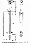
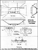
  1. In operating LVTs at sea it is often necessary to secure them alongside vessels. The following method has been tested and found to be the most practicable for securing LVTs alongside ship.

    1. The following sketch illustrates the lines to be used:

      Sketch: Securing LVTs Alongside Ships
      EXAMPLE   A
      B, C, D
      E, F
      Guess Warp.
      Distance Lines.
      Mooring Lines.

    2. In the above sketch line "A" Guess Warp is a 6" manila hawser which should be extending between chocks. Distance lines B, C, and D shall be 4" manila lines with eyes or bowlines in the ends through which line "A" is free to pass. Mooring lines E and F, bow and stern line of LVT, are to be 11/2" manila line. The mooring lines are passed around line "A" as indicated by the LVT crew and secured on the LVT. The distance line should be secured to place line "A" about ten feet clear of the water and within reach of LVT crew.

    3. This method reduces the danger of parting of bow and stern lines of LVTs in heavy sea and allows LVTs to tie up without depending on lines being passed from the ship.

»V-17«

    1. The above method is not recommended for use in connection with debarkation nets.

Section 10. Loading LVTs

  1. Loads for initial trips to the beach should be planned according to the need of the operation insofar as they can be foreseen. The initial phase for amphibian tractors will be considered concluded when demands are for supplies rather than personnel. Loading for this phase should consist of pieces of uniform size, weight, and shape where possible. Only enough personnel should be provided to stow and unload cargo under possible guidance of the LVT crew. Extreme care must be exercised in lowering cargo into LVT(2)s in order to prevent damage to the propeller shaft and bilge pump power take off. There is not sufficient room within the cargo compartment to unload large size nets. Nets should be lowered to the engine compartment and supported by ship boom until partially unloaded. All embarked supplies should be consigned to one destination, thus avoiding split loads. In many cases it will be necessary to transfer cargo from boats to tractors off shore or at the edge of a reef. If this is necessary, adequate working parties afloat must be provided.

Section 11. Communication

  1. Standard Navy boat signals will be used by LVTs in executing their maneuvers. Emergency signals may be devised.

Section 12. Supply, Repairs, and Servicing

  1. Ships transporting LVTs will carry reserves of fuel, lubricants, spare parts and repair facilities for LVTs as designated in troop Operation Orders. Ships will render service to any LVT in need of assistance irrespective of what ship transported it to the area. Until such time as an adequate beachhead has been seized and adequate facilities established ashore, LVTs will habitually return to their parent ship each night prior to darkness, for servicing, supply and repairs. If ships carrying LVTs are ordered from the area for any appreciable length of time, the repair facilities will be unloaded on the beach, prior to departure, at locations specified by the Troop Unit Commander. As soon as possible the repair unit will be moved ashore and establish a repair center.

  2. Ammunition and gasoline must be stowed on the top deck if welding is to be done aboard the LST. Permission to do any welding is to be obtained from the Captain of the ship.

  3. LCVPs will be designated as fueling and salvage boats. These boats should carry gasoline and oil and equipment for refueling LVTs. These boats should carry LVT mechanics and some spare parts to perform minor repairs and could also be used to tow stalled LVTs into shore or to the repair ship.

  4. LVT crews are continuously soaked by salt water while operating and to maintain their combat efficiency they should be given

»V-18«

    every consideration by the ship on which embarked, including hot food, water, medical attention, and an opportunity to bathe in fresh water if the tactical situation permits.

Section 13. General Description of DUKWs

  1. The DUKW described herein is an amphibious conversion of the standard Army 21/2-ton 6x6 truck. Thus the DUKW has similar automotive characteristics to the parent truck. In addition, it is equipped with an integral water-tight welded steel hull. The thickness of the bow is approximately 1/8", the bottom approximately 3/32", and the sides approximately 1/16". For land operations the vehicle uses six driving wheels -- driven by a six cylinder valve-in head-gasoline engine developing approximately 90 horse-power net. For water operations the DUKW is driven by a 25" diameter, 14" pitch, three-bladed weedless propeller, driven by the engine through the transmission and a water propeller transfer case. As a truck, the front wheels are steered in the conventional manner. When operating in the water, steering is accomplished by a rudder interconnected to the truck steering gear. There are two propeller shaft-driven bilge pumps of approximately 300 gallons per minute total capacity, and in addition there is a 25 gallon per minute hand pump. The normal crew is two men, consisting of the driver, who can completely operate the vehicle, plus an assistant driver or gunner.

  2. Each DUKW has sockets for installation of a scarf ring mount which can carry a .50 caliber machine gun. The present Army T/O supplies 13 machine guns and mounts per company of 50 DUKWs.

  3. Cargo space is 149" long, 82" wide, and approximately 28" deep. It has a 3/4" removable plywood floor which should be protected by the use of dunnage for any cargoes producing concentrated loads. Cargo space can be covered by a tarpaulin, either directly over the cargo or over removable steel bows. Capacity is 5,000 to 10,000 pounds of cargo, depending on conditions of operation. See paragraph 582 for details. If carrying personnel, the capacity is 25 fully equipped combat troops.

»V-18(a)«

  1. Capabilities:

    1. In the absence of adequate port facilities, the DUKW provides a most effective means of moving supplies from ship to dump, rail head or transfer point on shore.

    2. Large volumes of cargo can be moved through restricted beaches. Congestion at beach is eliminated as is the slow, difficult and dangerous cargo handling from beached boat to land conveyance.

    3. Beach performance is excellent, far exceeding that of other wheeled equipment. This results from use of large desert type tires with tire pressure controllable by driver while the DUKW is in motion.

    4. Surf performance is excellent due to low center of gravity simultaneous traction in water and on land. A ten-foot surf can be negotiated safely.

    5. The DUKW can negotiate offshore bars and reefs and coral which present an obstacle to landing craft.

    6. Each DUKW is equipped with a power winch with 10,000 pound line pull, and may be fitted with an "A" frame to serve as a temporary crane with a 5,000 pound capacity.

  2. Limitations:

    1. The DUKW is not an assault vehicle. Its relatively light skin affords no protection from enemy fire.

    2. DUKWs must operate in areas free from soft mud, swamps, marshes, quicksand, stumps, wreckage, wire, large rocks and boulders.

    3. Limited water speed makes long water hauls unprofitable.

    4. Limited reverse power, the fact that bilge pumps operate only when propeller shaft is turning forward, plus relative lack of boat handling experience on part of most drivers, make special DUKW mooring system imperative. (See Section 18 of this Chapter).

    5. Size of vehicle is small and freeboard is low in comparison to loads carried. Therefore, size and number of drafts and position of cargo must be suited to conditions existing. Design requires that all cargo be put in or out over the side. The advantages of a ramp or even a truck's tail gate are not available.

  3. Characteristics of the DUKW are:

    1. Dimensions:

      Length Overall 31'   0"
      Height -- top up 8' 11"

»V-19«

      Height -- top and windshield down 7'   6"
      Width -- overall 8'   4"
      Ground Clearance -- hull 1'   5"

    1. Freeboard and Draft -- 5,000# load:

      Freeboard to deck -- bow 1' 11"
      Freeboard to deck -- rear 1'   3"
      Freeboard to coaming 2'   6"
      Draft to front wheels 3'   8"
      Draft to rear wheels 4'   4"

    2. Weights:

      Fully equipped -- no pay load 15,000 pounds.
      Loaded 20,000 to 25,000 pounds depending on load.

    3. Maneuverability:

      Turning circle on land -- 70' diameter.
      Turning circle on water -- 40' diameter.

    4. Grade ability:

      Ascending 60% at 20,000 pounds gross weight.
      Descending 60% at 20,000 pounds gross weight.

    5. Performance:

      On land: 50 m.p.h. Maximum and average 4.0 gallons of gas per hour.

      Afloat: 5000 pound load, smooth water.
      Max. 2nd Gear, 2500 RPM -- 6.0 Land Mi. Speed using 6.8 gal. gas per hour.
                  2nd Gear, 2200 RPM -- 5.3 Land Mi. Speed using 4.4 gal. gas per hour.
                  3rd Gear, 1000 RPM -- 4.8 Land Mi. Speed using 3.2 gal. gas per hour.
                  3rd Gear,    800 RPM -- 4.0 Land Mi. Speed using 1.6 gal. gas per hour.
      Max. Reverse, 2.2 miles per hour.

Section 14. Employment of DUKWs

  1. The prime function of the DUKW is to handle supplies across undeveloped beaches. As compared to landing craft, the advantages of DUKWs is greatest when the water haul is short, when the beaches are flat causing the landing craft to ground in comparatively deep water, where there are off shore bars or shoals, and whenever coral is encountered.

    1. In cases where roads are bad, or the distance from beach to dump is greater than two miles, DUKWs will be obliged to spend a large proportion of their operating hours on land. This will waste their amphibious qualities, and thus slow down ship discharging

»V-20«

      rates. Whenever possible, land vehicles should be used for hauling cargo on long land runs, and cargo should be transferred to them from DUKW at a transfer point close to the beach.

    1. Extremely effective use of DUKWs can be made where shore facilities in a harbor or have been heavily damaged or blocked. A suitable landing apron will permit continuous flow of DUKWs from shipside to rail head, depot or transfer area ashore. The smooth water of the harbor with prepared landing spot permits maximum loads on each DUKW. 105mm howitzers and other similar and smaller artillery can be landed in DUKWs, which also carry the gun crew, some ammunition and "A" frames so the DUKWs can unload each other. The DUKW makes an excellent prime mover, having better sand ability than the standard trucks. DUKWs should be replaced by the standard prime movers as rapidly as possible to make the DUKW available for the amphibious supply work.

  1. In planning on use of LVTs and DUKWs, the work should be apportioned so that the LVTs do the assault work, and the operations involving mud, swamps, heavy brush, and land impassable to wheeled vehicles. DUKWs should not participate in assault work, but should do the normal supply work as they can operate more efficiently and with a minimum of damage to roads. DUKWs are well suited to casualty evacuation. They can take 12 stretcher cases with attendant, or up to 40 walking wounded. By use of tarpaulin, casualties can be sheltered during trip from casualty station directly to shipside. If LSTs are used, the DUKWs can drive directly in over the ramp.

Section 15. DUKW Control in Large Operations

  1. Assault Phase:

    1. During the initial assault, DUKW Companies operate as separate units attached to elements of the assault force for the service thereof.

    2. They will be combat loaded with troops, Shore Party equipment, guns and ammunition in accordance with prearranged schedules.

    3. In the assault, DUKWs with guns or other heavy equipment will be landed and immediately unloaded by "A" frames. DUKWs will then tow guns to their initial positions.

      1. Upon the landing of the normal prime movers, DUKWs are automatically released to DUKW Battalion Headquarters, and accordingly will report to DUKW Beach Control Point.

      2. DUKWs reporting to DUKW Beach Control Point from artillery firing positions will bring either a messenger or a sketch of the gun location to facilitate location thereof by the normal prime movers.

»V-21«

  1. Supply Phase:

    1. Upon reporting to DUKW Beach Control Point, the assault phase is ended for the DUKW, and thereafter all DUKW operations are coordinated and supervised by DUKW Battalion Headquarters, which will set up a Command Post in a suitable area.

    2. No DUKW can be dispatched on a mission unless it is cleared through the DUKW Command Post.

    3. DUKW Command Post duties are as follows:

      1. To establish liaison with higher authority and to act upon orders received from them. To obtain from higher authority the following information:

        1. Locations and descriptions of ships to be unloaded.
        2. Type of cargo to be handled from various ships by DUKWs.
        3. Overlay showing dump locations.
        4. Time unloading operations will begin.
        5. Type and condition of road marking for both day and night operations.

        6. System of ship lighting during hours of darkness.

      2. To be responsible for overall recommendations affecting DUKW operations arising from weather and other conditions.

      3. To keep a continuous check and records on DUKW movements, in order that higher authority can have accurate information on present and future DUKW availability.

      4. To establish control points at the following places:

        1. At the beach.
        2. On ships.
        3. At the dumps.
        4. At the DUKW assembly area,

        and to maintain close contact by radio, telephone or runner with these points.

    4. DUKW Beach Control Point will be set up on that portion of the beach chosen for the entrance of DUKWs into the water, preferably at a separate point from the landing craft. The DUKW Beach Officer's duties will be:

      1. To make arrangements for the laying and maintenance of beach matting as necessary.

      2. To make arrangements for the proper marking of the DUKW beach, and to set up front and rear range markers if they will aid DUKW operators in keeping a straight water course to and from the beach.

»V-22«

      1. To check on the seaworthiness of DUKWs before entering the water, i.e. bilge plugs installed, hull drain valves closed, hatches closed and dogged down, all equipment on board, etc.

      2. To dispatch DUKWs to the ships at such a rate that there are never more than two DUKWs waiting for their loads at each hatch. If operational DUKWs are held ashore pending dispatch, they will form a "cushion" in a suitable area close to the Beach Control Point. Here crews can refuel their DUKWs, receive rations when necessary, and can perform their "During Operations Maintenance" under the supervision of a senior non-com.

      3. To insure that DUKW operators can identify the ship which they are to unload and know the recommended route to it.

    1. Ship Control Point will be set up on every ship discharging into DUKWs. The first DUKW to be dispatched to a ship will take with it a DUKW officer, DUKW rigging assistants and DUKW mooring equipment. Their duties will be:

      1. To assist in rigging the ship in accordance with the approved DUKW mooring system.

      2. To be responsible for DUKW mooring equipment and to keep constant check on its condition.

      3. To decide on the manner of loading and amount of load given to the DUKWs.

      4. To establish close liaison with the TQM and the master of the ship, and recommend to them any actions which may accelerate the unloading, such as the making of a lee, and the shifting of anchorage when it will shorten the Ship-to-Shore distance.

      5. To supervise the coming alongside and mooring of the DUKWs.

      6. To inform DUKW Command Post continuously concerning details of the off-loading.

      7. In discharging DUKWs from LSTs or other ramp vessels while afloat, to stand at the head of the ramp and insure that all DUKWs enter the water in accordance with the approved technique. (See paragraphs 569 and 570).

    2. Dump Control Points will be set up at each dump where DUKWs are being unloaded, or a DUKW officer can circulate between the dumps. His duties will be:

»V-23«

      1. To expedite the turn-around of DUKWs, and to work closely with dump officers in the use of fast unloading methods such as hog troughs and "A" frames.

      2. To inform the DUKW Command Post continuously concerning details of unloading. If DUKWs are being delayed considerably, thus slowing down ship unloading time, he should recommend to higher authority through DUKW Command Post that transfer points be setup. A transfer point should be close to the beach and should have means for the rapid transfer of loads from DUKWs into land trucks.

    1. DUKW Assembly and Bivouac Area will be set up in an area considered safe from enemy aerial and ground attack. This area is primarily intended for non-operating DUKWs and their crews. The DUKW Officer's duties will be:

      1. To be responsible for the presence in the assembly area of all non-operating DUKWs and their crews.

      2. To supervise, with the cooperation of DUKW maintenance officers, all DUKW maintenance, except "During Operations" duties.

      3. To make arrangements for food, latrines and billets for DUKW personnel.

      4. To inform the DUKW Command Post on the status of all DUKWs in the assembly area.

      5. To require the highest standards of passive air defense by dispersal and camouflage of vehicles and personnel.

      6. To require the highest standards of security against enemy attack.

Section 16. Operating With LSTs

  1. DUKWs should be driven aboard frontwards, the only exception being as mentioned in paragraph 544 below. Where possible, particularly when loading for a long trip, the loading should be made from dry land. This is necessary to prevent serious corrosion of brake mechanisms and other parts while the DUKW is stationary for a long period. DUKWs can also be driven up the ramp to the top deck on LSTs so fitted. The guides for the ramp to the upper deck should always be hung up out of the way when operating from the tank deck. In the normal unloading, the DUKWs leave the LST stern first.

  2. Backing on Board:

    If the loading plan places 3 DUKWs abreast immediately inside of the ramp opening (See Fig. 7 below) the last DUKW on each side should be backed on board to make it possible to get in and out of the corners near the ramp opening. DUKWs can be backed aboard easily on land,

»V-24«

    but afloat it requires smooth water and a skillful driver. It is most important that the center part of the ramp be clear of obstructions so that propeller guards will not be damaged on DUKWs so fitted, either when backing on board or going off frontwards. Also the pintle hook on the DUKW must be turned on its side to provide maximum clearance. The bolt thru the emergency ramp cable fitting at centerline of LST ramp, should be ground off as near to flush as possible. In all cases go on or off the ramp slowly, and when going off frontward, don't engage the propeller until after clearing the ramp.

    Figure 7. DUKW loading plan for LST.
    Fig. 7
    Plan showing maximum of 22 DUKWs on tank deck of LST. Numbers indicate order in which the DUKWs come aboard. No. 19 and 20 only, are backed on. All DUKWs leave in opposite order to which they come on board.


    Figure 8. DUKW loading plan for LST.
    Fig. 8
    Plan showing maximum of 21 DUKWs on tank deck of LST. All DUKWs are driven aboard frontwards.

  1. Lashing. The three bow shackles, and the stern pintle hook, plus the 2 fender eyes on each rear deck corner, are the most suitable lashing points. The 2 lifting eyes and one mooring eye on each side are

»V-25«

    strong fore and aft lashings, but not good for side pulls. Do not use bow fairlead or either bow or stern davit eyes. Park the DUKWs in low range reverse and set hand brake.

  1. Tire Pressure. Tires should be inflated to 40 pounds and individual valves shut (on DUKWs equipped with central tire control). Inspection should be made daily for leaking tires, and repairs effected when necessary. Individual valves should be opened to equalize tires (after inspection) and when necessary, tires inflated to maintain 40 pounds pressure.

  2. Maintenance.

    1. Gasoline tanks should be filled before loading.

    2. After loading, bilges, including 3 drives shaft housing, should be drained, bilges cleaned and all plugs replaced and valves closed.

    3. Run engine about 10 minutes every second day.

    4. Operate propeller, and winch drive shaft, briefly each time engine is run.

    5. Perform "Weekly" maintenance as outlined on "Minimum Drivers Weekly Maintenance", reproduced herewith. (Exclude land and water test runs). Do not drain any part of the fuel system, or replace any gasoline except when directed by company officers. At such times, LST deck fans must be running, and extreme care must be used to see that no gasoline is spilled.

    MINIMUM DRIVER WEEKLY MAINTENANCE
    REFER TO TM 9-802 & LUBRICATION ORDER #505 FOR DETAILS

    DRAIN WATER FROM FUEL TANK & FILTER, & CHECK SYSTEM FOR LEAKS.
    CHECK FUEL, OIL, & WATER - IN ENGINE, TIRE PUMP, AND SPARE CANS.
    CHECK OIL LEVEL IN TRANSMISSION, MAIN & PROP.TRANS.CASES, WINCH WORM HSG.
    OIL HAND AND FOOT THROTTLE, CHOKE, STARTER LINKAGE & 2 CUPS ON TIRE PUMP.
    LUBRICATE CONTROLS FOR MAIN & PROPELLER TRANSFER CASES, BRAKES & CLUTCH.
    LUBRICATE V-STRUT & BILGE PUMPS, CHECK DRAIN VALVES & PLUGS ALL TIGHT.
    CHECK BATTERY WATER & CRANKCASE & CARB. AIR CLEANERS - CLEAN RADIATOR.


    MAKE LAND TEST RUN. CHECK FOOT BRAKES AND COMPASS ADJUSTMENT.
    CHECK IDLING SPEED FOR 500 R.P.M. CHECK FOR LOOSE MANIFOLD NUTS.

    MAKE WATER TEST RUN. CHECK FOR LEAKS. CHECK OPERATION OF PUMPS.
    CHECK FOR 2350 MINIMUM R.P.M. & NOT OVER 185° TEMPERATURE AT FULL THROTTLE.

    CLEAN & DRAIN BILGES, LUBRICATE 3 "U" JOINTS THRU HOUSING DRAINS.
    CHECK 4 BREATHER TUBES, 6 HOUSING SEALS & INTER-HOUSING DRAIN.
    REPLACE PLUGS, CLOSE DRAIN VALVES. REMOVE ANY WATER IN PILLOW BLOCK, DIFFERENTIALS AND FRONT AXLE "U" JOINTS - CHECK LUBRICANT LEVELS.
    LUBRICATE V-STRUT, INTER-AXLE SHAFT (3), FRONT SPRINGS (6), DRAG LINK (2), TIE ROD (2), TIRE INFLATION HUBS (6), BILGE PUMPS (2), STUFFING BOXES (2).
    OIL OUTSIDE OF FRONT AXLE "U" JOINTS, CHECK OIL LEVEL IN AIR CLEANERS.
    GREASE 3 WINCH POINTS - OIL & REWIND CABLE. OIL PUMP DRIVE CHAINS.
    CLEAN & PAINT RUSTED PARTS. CLEAN & OIL OUTSIDE OF FRONT AXLE "U" JOINTS.
    CHECK & STOW TOOLS & EQUIPMENT. CLOSE HATCHES. RIG CAB TARPAULIN.

»V-26«

  1. LST Marking. During the unloading operations, much valuable time can be lost by the DUKWs going to the wrong LST. For that reason it is extremely helpful to have large numbers, at least 6 feet high (with a line thickness not over 1/10 the number height) painted on port and starboard bow and port and starboard quarters of the LST. (See Chapter XXXVI).

  2. Ramp Curbing Corner Guards. The outboard corner of the ramp curb (see page V-30) is very dangerous and can easily cut a hole in the bow of a DUKW when landing. It is extremely important that this corner be guarded. The simplest field expedient is to use 1/3 of a salvaged tire, fitting it over the corner, and wiring it securely thru small holes drilled in ramp curb, preferably with additional canvas or rope padding underneath the tire. A triangular shaped rope matting would also be helpful. A suitable type of removable curved steel guard to be used in conjunction with a tire is the best protection.

  3. Ramp Obstructions. Any obstructions that extend above the ramp cleats should be removed, and surface ground smooth to protect DUKW hull and tires. Inner face of ramp curb, and passageway into tank deck, should be kept clear of any sharp obstructions. The belt thru the emergency ramp cable, fitted to ramp center, should be ground off as nearly flush as possible.

  4. Distance from Shore. Due to the slow speed of the DUKWs, it is imperative that the LSTs take station as near the shore as tactical situation will permit. By staying far off shore, danger in many cases will be increased, as the unloading period will be drawn out many times the period that would be necessary if a berth nearer shore were used. When strong currents must be negotiated there is a resultant loss in the DUKWs speed, placing more emphasis in nearness to shore, also suggesting initial unloading at a point upstream from desired landing point. (See DUKW speed, paragraph 571).

  5. Ramp Angle. It is most important that the DUKW wheels or bow do not hit against the extreme lip of the ramp. To prevent this, the minimum submersion should be approximately 4 feet. In rough water, or when the LST is light forward, relatively steep ramp angles will be necessary to insure this submergence. On the other hand, a flat ramp angle makes landing and launching easier. Therefore, in smooth water, and when it is possible to ballast the LST forward tanks, the 48 inches depth over the lip of the ramp can be obtained with the ramp considerably above the bottom stop position.

  6. Ramp Cables, Shores and Doors. Regardless of whether shores are employed or whether the ramp is set so it is down against the lower stop, it is important that either the hosting cables or auxiliary cables (preferably covered with pipe) be kept tight to prevent the DUKW straddling one side of the ramp. It is also important that the doors be kept as close into the sides of the ramp as possible to prevent a DUKW getting off the edge of the ramp under the support cables. Keep the DUKW wheel house covers securely in place and in good condition, and they help prevent wheel houses catching on the ramp cables.

»V-27«

  1. Keep Ramp Opening Clear of Personnel. The curious crowd which normally collects in the ramp opening, tends to confuse the DUKW driver, and frequently causes him to stop prematurely, perhaps in a dangerous position. The officer in charge of directing the landing (or launching) should stand clearly in the center. The rest of the opening should be kept absolutely clear.

  2. Handling of Ship during DUKW Launching. Due to the slow reverse speed of the DUKWs it is imperative that the LST have no headway when DUKWs are launching or landing. Where a strong current might take the ship out of position, operations could continue with the LST maintaining sternway up to 21/2 to 3 knots. In all cases, whether anchored or not, the LST engines should be used as much as possible to prevent yawing, and to eliminate cross currents or cross seas over the ramp.

  3. DUKW Loading. The total payload should center approximately 2 feet forward of the center of the cargo space. It should not be more than 5000 pounds where conditions are unknown or where conditions are known to be difficult. Under combat emergency, where conditions are favorable, 7500 pounds may be carried. For ship launching operations, total payload should never exceed 7500 pounds. (See Paragraph 582.)

  4. Control. No DUKWs will be launched from or landed on the LST without clearance from the ship's officers. The actual direction of the DUKW at time of launching or landing will be by an officer of the DUKW Company, will be stationed at the head of the ramp on the tank deck.

  5. Launching.

    1. Pre-Launching Check.

      1. Tire pressures correct for expected landing conditions.

      2. Supply of gasoline, oil and water, including spare supply.

      3. Weight of payload not excessive for conditions as they exist.

      4. That load is properly placed and secured.

      5. Inside of hull clean and dry, all plugs in place and drain valves closed.

      6. All DUKW standard equipment and tools are on board and in place.

      7. Hull is free from leaks. Hold for repairs when necessary.

      8. Cab top removed, windshield down, bow surf plate folded down on deck.

      9. Bow hatch, engine hatch, auxiliary air intake, rear hatch and 2 winch cable fairleads in coaming, all are tightly shut.

»V-28«

Figure 9. LST Ramp Diagram
Figure 9.
L.S.T. Ramp

»V-29«

DETAIL
L.S.T. Ramp Curb corner protection for use with DUKW. Guards and bumpers must be removed to tightly close ramp.

(1) Section of Tire over corner -- wired to hole drilled in gutter.

Figure 10.1 Section of Tire over corner -- wired to hole drilled in gutter.

(2) Rope Fender Made to Shape -- Wired to hole drilled in gutter.

Figure 10.2 Rope Fender Made to Shape -- Wired to hole drilled in gutter.

(3) Removable Guard of 4" x 1/2" angle or similar angle or channel made to shape and protected with tire or shaped rope fender secured to guard.

Figure 10.3 Removable Guard of 4

Figure 10

»V-30«

      1. Rear closure set up -- except in case of 105mm Howitzer or special loads that prevent its being set up, in which case cargo tarp must be rigged tightly around rear coaming to keep out water when backing down the ramp.

      2. When loaded, cargo tarp must always be rigged over at least the rear half of cargo space. In rough weather cargo tarp must completely cover cargo space.

      3. Engine well warmed up -- cooling passages all clear.

      4. Driver understands his instructions and objectives.

    1. At the actual launching, the following details should be carefully followed:

      1. Personnel in DUKWs temporarily crowd forward to lighten the stern while descending the ramp.

      2. Front wheels engaged and transfer case in low range.

      3. Transmission in reverse. (First speed for forward launching).

      4. Propeller drive in reverse (overdrive) position. For forward launching propeller should not be engaged until stern of DUKW clears the ramp.

      5. Bilge pump manifold right rear valve open. All others shut.

      6. Set pintle hook crosswise -- necessary only for forward launching.

      7. Release emergency brake.

      8. Do not depress clutch after starting down ramp. Engine is the best possible control of your speed. To guard against inadvertently depressing clutch, place left foot on the floor alongside the pedal.

  1. DUKW Speed. A DUKW in first-class operating condition will make 6.5 land miles per hour traveling light and in smooth water. From this one should deduct 1/10 of a mile for each 1000 lbs of load carried, also 1/10 of a mile for each foot of wave height, and probably 3/10 for possible mechanical deficiencies (slow governor, lame engine, bent propeller, etc.) These figures should help in laying out a course to the shore or to control boats.

  2. Loading on LST. When approaching the LST preparatory to loading, the driver should check the following:

    1. Bilges pumped as dry as possible.

    2. Rear closure up. When loaded, tarpaulin rigged tightly over at least rear half of cargo space.

»V-31«

    1. Tire pressure 25 pounds.

    2. If loaded, that load is properly placed and secured.

    3. Keep about 50 yards in front of LST ramp, and be alert to receive signal to land.

    General -- Loading.

    1. Lower bow surf plate and windshield when you get signal to land.

    2. Engage transfer case in low range.

    3. Check that front wheel drive is fully engaged.

    4. Shift transmission to first speed.

    5. Shift propeller control to reversed (overdrive) position.

    6. Approach the ramp keeping directly in line. If the LST is swinging, allow for the swing -- lead it by heading enough towards the side to which it is swinging, so that the DUKW will be directly in front when the ramp is reached. Step on the gas when a turn is to be made. Turn the steering wheel in time, also straighten out ahead of time or the DUKW will swing too far. If the DUKW strikes the cables, slip the clutch until the DUKW bounces back sufficiently to enable the bow to get on the ramp. Do not reverse unless so directed by the officer controlling the landing from the tank deck of the LST.

    7. When on the ramp, steer down the center and do not stop unless directed, until on the down grade inside.

    After Loading on the LST.

    1. Move DUKW to position as directed.

    2. Deliver any messages from shore. Make known any special needs so materials can be secured without delay.

    3. Drain hull and close valves.

    4. Get necessary fuel, water or oil. Do not fuel on tank deck without permission.

    5. If landing was rough, inspect carefully for damage and make any necessary repairs. Rags, wooden wedges or plugs and seam compound will serve when it is out of the question to weld. A tarp can be securely lashed over a fairly large hole to permit safely reaching better repair facilities.

  1. Speed up DUKW Operating Cycle. With the exception of driving slowly down the steep part of the ramp, all phases of DUKW operations should be accomplished without delays. Some 75 to 300 DUKW round trips will be needed to unload the LST. Each round trip has a number of key

»V-32«

    points from which wasted time can be eliminated. When on DUKW is going down the ramp, the next should be moved quickly to the top of the ramp so it is ready to follow at a 10 to 15 second interval. When one DUKW is landing, the next DUKW should be brought in close so that as soon as the landing DUKW is in a safe place, the next will reach the ramp. If a rendezvous circle is used, it should be kept small and close. Where there is current, the circle can be dispensed with and the DUKWs can stay in position driving slowly ahead, watching for their turn to land. The importance of saving a minute here and there on each DUKW trip is vital.

  1. Landing Alongside. On LSTs carrying pontoons it is important that DUKWs be kept away from the dangerous area from which the DUKWs might get forced under the pontoons. Thus if the LST is anchored by the stern or is making sternway, landing should not be made at the stern, as it is easy to be forced under the pontoons, which may then do serious damage to the personnel and equipment. However, landings at either side of the bow would be perfectly safe, provided the doors are kept in close to the ramp. On the other hand, if lying to a bow anchor or moving ahead, the stern would be the safer position to land.

  2. Fueling. The first trip to shore should be started with a full gasoline tank and two full five gallon gasoline cans on rear deck. The maximum fuel consumption should be under seven gallons per hour, the normal average approximately half that figure. When on shore, if the tactical situation permits, gasoline should be put in the tank from the extra five gallon cans or from any other available source. In order to save time and bottle-necking, a supply of filled five gallon cans should be available on shore, also on the LST. It is not advisable to pour in the gasoline on the tank deck of the LST unless it is absolutely necessary. Then it is important that ventilation fans are running and that every precaution is taken to avoid spilling fuel. Each time a DUKW lands on the LST, it should leave any empty five gallon cans and pick up in exchange cans that have been previously filled. It is advisable that the five gallon cans be filled on the weather deck of the LST. When sea conditions will permit, fueling can also be accomplished by a hose overside to the most sheltered landing place alongside the LST.

  3. Handling Ammunition. When ammunition is carried on the tank deck under the DUKWs, after the DUKWs have gone overboard for their initial trip to shore, the dunnage should be removed from one side to the center line, leaving enough dunnage so that the DUKWs returning to load can drive in, in column, using the side from which the dunnage has not been removed. Ammunition should then be loaded on the DUKWs. This can be expedited by having a pile stacked in advance next to each position where a DUKW will be parked. The greatest emphasis must be laid on loading the last DUKW aboard as it must be the first to leave. The number of men in the loading crews should be graduated down for successive DUKWs, the largest crew loading the last DUKW aboard, and the smallest crew loading the first DUKW aboard. Assuming six DUKWs

»V-33«

    arrive for a load of ammunition and the first DUKW boards the LST at 0900, the DUKWs should enter not over thirty seconds apart, placing the sixth DUKW on board 0902:30. Assuming five minutes to load the sixth DUKW, it then leaves at 0907:30. Assuming the DUKWs leave at thirty second intervals, there will have been 6, 7, 8, 9, and 10 minutes for loading DUKWs 5, 4, 3, 2, and 1 respectively. In an ideal operation, if the round trip, including loading and unloading can be made in an hour, and if the LST carried 24 DUKWs, a group of six would be loaded by the LST once very 15 minutes. There would be 24 trips leaving each hour and assuming 31/2 tons average load, that would be 84 tons per hour. The ideal set-up would have six DUKWs loading on the LST, six loaded DUKWs half way to the shore destination, six DUKWs unloading at destination and six empty DUKWs half way back to the LST.

  1. Miscellaneous Cargo: Jeeps or M-29-Cs can be loaded by being driven up over the stern of a DUKW on temporary ramps 12 feet long. 10 foot ramp must be used in the DUKW cargo compartment and DUKWs rear deck and rear coaming must be amply protected with dunnage. A DUKW with an "A" frame could be used on the top deck to lower heavy loads through the main hatch on to vehicles on the tank deck. However, this should only be done where there is no other expedient available, as it is slow and ties up one otherwise needed vehicle. Two LST ammunition davits can be used, one at each forward corner of the main hatch.

  2. Anchoring: If anchored during ramp operation, it is important that the stern anchor be used. Never operate from ramp when anchored by the bow.

Section 17. Operating From LSDs, LSVs, LSMs

    1. Operating from LSDs: The details covered in Section 16, Operating with LSTs, is generally applicable to LSD operations. An important exception is that where the tactical launching will be made by flooding, the DUKWs should be put aboard facing the stern, so they can swim out driving bow first. Note that the main deck of the LSD can accommodate 47 DUKWs.

    2. Operating from LSVs: The details covered in Section 16, "Operating with LSTs" is applicable to LSV operations. A 4" extra heavy pipe tripod 8 feet high should be welded on the LSV ramps to protect each outer sheave. This tripod should be heavily wrapped with rope to provide a cushion. A removable section of 5" x 1/2" angle should bridge the cut out section of the ramp curb on each side. 29 DUKWs can be loaded on the vehicle deck of LSVs up to LSV #3, and 31 on the latter ships, all facing the bow. Additional DUKWs can be carried on the main deck and launched by the main derrick.

»V-34«

    1. Operating from LSMs: The details covered in Section 16, Operating with LSTs, is generally applicable to LSM operation with the following supplemental information:

      1. Preparation for loading: The deck of the LSM must be completely clear of all lolose gear. The inboard portion of the gun tub platforms must be folded up. If landing mat is carried, it should be placed flat on deck, keeping it back from ramp opening so its edge will not act as an added obstruction during the steep climb up the ramp. The mat should be placed so it will cover a minimum number of deck lashing eyes.

      2. Maximum number carried: It is possible to carry 10 DUKWs on an LSM, rather than 9 as stated in O.N.I. publication #226.

      3. Details of loading: The DUKWs are all driven aboard frontwards, (DUKW bow toward LSM stern) in the order and to the positions indicated in sketch below.

        Sketch: Positions to permit maximum of 10 DUKWs on LSM.
        Positions to permit maximum of 10 DUKWs on LSM.

      4. Loads must clear gun tubs: DUKWs one, six and seven must not have high loads that would interfere with the hinged portion of the gun tub platforms being folded down after the DUKWs are in place. Loads in these particular DUKWs must not be above a clearance line running level with the top of the coaming at the rear cargo bulkhead. This line would be six inches above top of coaming at forward cargo bulkhead. This excludes such loads as 105mm howitzer or other light artillery or small vehicles, from DUKWs one, six and seven.

      5. Gun tub supports: When the hinged portion of the gun tub platforms is folded down over DUKWs one, six and seven, it will not be possible to use the normal support braces, but rather, the hinged portion must rest on blocking on the DUKW cargo or in the DUKW cargo space.

»V-34(a)«

    1. DUKW tarpaulins: The cargo space tarpaulins must be rigged without bows on DUKWs one, six and seven. The tarpaulins must be placed directly over cargo space, supported by cargo supplemented by temporary blocking for frame to prevent water catching.

    2. Lashing on deck: Due to the high angle of roll (as much as 35 degrees) special care must be taken that DUKWs are securely lashed. The three bow shackles and the stern pintle hook, plus the two fender eyes on each rear deck corner are the most suitable lashing points on the DUKW. The two lifting eyes and one mooring eye on each side are strong enough for fore and aft lashings, but not good for side pulls. Do not use the bow fairlead or either bow or stern davit eyes. DUKWs should be parked in low range reverse with hand brake set.

    3. Steadiness of the ramp: The numerous perforations in the LSM ramp reduce the tendency for the ramp to be lifted by the action of the waves as compared to the LST.

    4. Anchoring: If anchored during ramp operations, it is important that the stern anchor be used. Never operate from the ramp when anchored by the bow.

Section 18. Mooring at Shipside

  1. It is of particular importance that all ships discharging into DUKWs accurately follow out the details set forth in this section. The unloading operation involves a continuous sequence of moorings along side by the DUKWs. In view of their small cargo space, accurate and rapid positioning under booms is necessary.

»V-34(b)«

    Figure 11. Mooring rig, showing spring lines and messenger lines.
    Figure 11.
    Mooring rig, showing spring lines and messenger lines.

  1. Spring Line Mooring. The DUKW will be moored at shipside by a single spring line 31/2 to 41/2 in circumference and about 100 feet long. This spring line will be secured on the deck of the ship. The forward end of the line carries a mooring hook which is engaged in the DUKW mooring eye. A messenger line of the same size as the spring line will be fastened to the string line 4 feet back of the mooring hook and will lead to the deck of the ship directly above the mooring position. If necessary, the spring line will be parceled to prevent chafe at the ship's deck. Where the ship is rigged with a guest warp, it may be convenient to attach the individual spring lines to the guest warp rather than to lead them to the deck of the ship. When working with the guest warp, the individual spring lines can be considerably shorter. About 50 feet length will be sufficient. The messenger lines will also be rigged.

    Figure 12. Mooring Hook
    Figure 12
    Figure 13. Mooring Hook
    Figure 13
    Figure 14. Mooring Hook
    Figure 14
    Alternate types of mooring hooks that may be used. To facilitate night operation, hooks should be painted with phosphorescent paint, or white paint.

»V-35«

  1. For loading DUKWs, cargo booms must be rigged so that the load centers only five feet outboard from the ship's side when hanging from outboard booms. Booms over the #1 hatch should be rigged as far aft from bow flare as possible. Booms over the #5 hatch should be rigged as far forward from stern flare as possible. All booms should be rigged to keep DUKWs clear of dangerous hull obstructions, and to provide all possible space between adjacent berths. Double rigged hatches should be worked from opposite sides except when rough water necessitates operation from the lee side only. Spring lines must be adjusted so load comes down directly over the center of DUKW cargo space.

  2. Approaching the Ship.

    Figure 15. Proper approach to mooring position from astern.
    Figure 15.
    Proper approach to mooring position from astern.

    When a DUKW approaches a ship to receive or deliver a load, it should take up a position not more than a hundred feet from the position where the DUKW expects to moor. Immediately upon receiving a signal to moor, the DUKW will approach the mooring position at approximately a 45° angle from astern. See Figure 15. As it approaches the mooring hook, the DUKW will be slowed down and turned parallel to the ship about one to three feet away from the ship's side. The assistant driver will reach the mooring hook from the aisleway and quickly hook it into the DUKW's mooring eye, with the point of the hook towards him.

  3. The DUKW will then be driven slowly ahead against the spring line. When the line come[s] tight, the rudder is turned away from the ship, so that the DUKW is held evenly against the ships side. The hand throttle can then be set to supply sufficient power to keep the spring line tight. When mooring near the bow of the ship, careful adjustment of the rudder is necessary to hold the DUKW close to the ship's side. If the rudder is turned all the way away from the ship, the bow of the DUKW will be forced outwards by the current and waves.

»V-36«

    The steering wheel should be set so that the DUKW stays close, and then lashed with a short length of line when necessary.

  1. Positioning Under Flare.

    Figure 16. Positioning Under Flare.
    Figure 16.

    Where there is considerable flare abreast the #1 and #5 hatches it will be necessary to steer the DUKW during loading, swinging the stern out to get under the load and to keep out from under the overhang (See Figure 16). In cases of extreme flare at #5 hatch particularly in rough water, it may be advantageous to lead this spring line forward, engaging the hook in the inside bow lifting eye and using little or no power after picking up the hook. Under these conditions an additional stern line may be helpful but it will need constant attention due to its unfavorable angle.

  2. In smooth water such as exists in harbors, DUKWs can be moored in pairs. This system is particularly helpful where there is considerable flare, as abreast #1 and #5 hatches. The procedure is as follows:

    1. Before coming alongside, two DUKWs tie up by lashing together their mooring eyes. They then maneuver like twin motored boat and the inside DUKW secures the mooring hook to his mooring eye in the approved system.

    2. When the DUKWs are mooring the outside DUKW can shut off his motor and the inside DUKW turns the rudder and sets the hand throttle as usual. The crews of both DUKWs assist in the handling of the cargo.

    3. When they are both loaded, they move away from shipside before separating.

    4. It must be noted that this system is not practical in rough water.

»V-37«

  1. Fender Protection. If a ship has a guard rail or rough guards over hull outlets, rope or mat fenders should be rigged by the ship to protect the DUKWs. A floating log fender is very practical. If a ship has reasonably smooth sides, the DUKWs fenders should give sufficient protection.

  2. Making a Lee.

    Figure 17. Ship making a 20 degree lee.
    Figure 17.
    Ship making a 20° lee.

    In extremely rough weather, the ship will do all possible to provide approximately a 20° lee.

  3. When DUKWs and other types of craft are working on the same ship, it is desirable to divide the work by hatches, so that a hatch rigged for DUKWs will be available when DUKWs come for a load. In this connection it should be noted that LCM and LCVP can moor satisfactorily on gear rigged for DUKWs, but DUKWs cannot operate effectively using mooring methods normally employed for LCM and LCVP. This is because the DUKW only pumps when propeller is being driven ahead and also because the DUKW has a weak reverse making it difficult to hold in position with the boat technique.

  4. When the current or tide runs by the ship from stern to bow, due to the ship being aground or moored to a dock, the mooring rig will be reversed, so that DUKWs will come in head to the current. In all cases, spring lines must be rigged to lead aft from the DUKWs.

  5. Whenever the DUKW is going to moor, the bow surf plate will be folded back. When the plate is set up it extends beyond the bow and bow fenders, and may be damaged. In addition, rear surf shield should be folded down before mooring.

  6. If the engine stops and cannot be started while the DUKW is moored, the DUKW should cast off immediately, even if this necessitates cutting the spring line with a knife or an axe. After drifting clear of the ship, the signal for assistance should be displayed and the DUKW should await tow. If no tow is in sight, the DUKW should anchor.

»V-38«

  1. The Procedure for Leaving a Mooring is as follows:

    1. Favorable Conditions. Under favorable conditions, the clutch should be disengaged and the spring line unhooked as soon as it is slack. The bow should be pushed off (from the aisleway) and when the bow has swung away from the ship the clutch should be engaged to drive the DUKW ahead. Do not swing away sharply or the stern will hit the ship and pull the DUKW back alongside. (See Figure below).

      Figure 18. Leaving a mooring under favorable conditions.
      Figure 18.

      (1) Moored alongside.
      (2) Drop back sufficiently to permit unhooking.
      (3) Push off by hand from aisleway before starting ahead.
      (4) Drive ahead, turning away gradually so stern does not swing against ship as this would tend to pull you on alongside again.
      (5)) All clear -- take described course.

    2. Unfavorable Conditions. If tide or other conditions make it impossible to leave the ship's side in the above manner, the steering wheel should be turned toward the ship before the DUKW is unhooked and the propeller should be driven ahead to swing the stern well clear. Then the DUKW should be unhooked and backed away with the propeller in reverse and the wheels in high transfer. When well clear, the DUKW should be turned away and driven with the wheels disengaged.

      Figure 19. Leaving a mooring under unfavorable conditions.
      Figure 19.
      Leaving a mooring under unfavorable conditions.

»V-39«

      (1) Moored alongside.
      (2) Driving ahead, wheel turned toward ship forcing stern out.
      (3) When this position is reached, unhook mooring line and back away.
      (4) When this position is reached turn DUKW away from ship and drive ahead.
      (5) All clear -- take desired course.

Section 19. Cargo Handling

  1. PAYLOAD. A most important feature of cargo handling is to carry the correct weight of pay load. This weight must be governed by operating conditions. In determining payload, all personnel, personal gear, spare gasoline, oil, water, parts, dunnage, nets, pallets, and all items that are not part of a standard DUKW must be counted as part of the payload. The above persons and items usually weigh from 500 to 1500 pounds; 1000 pounds should be considered as average. Total payload should center about 2 feet forward of center of the cargo space and should normally not exceed 5000 pounds. However, under combat emergency and when conditions are such as indicated below under FAVORABLE Conditions or IDEAL Conditions, the payload may be between 5000 and 10,000 pounds. More than 10,000 pounds, however must never be carried.

    1. Difficult Conditions: Operating under DIFFICULT CONDITIONS, payload should not be over 5000 pounds. The term DIFFICULT will apply to all operations involving use of untried landing sites unless reconnaissance has definitely indicated conditions to be FAVORABLE. It also applies to surf at shore over 3 feet, wind over 15 miles per hour (white caps) and when the wave height at shipside is over 3 feet. In addition it applies to operations involving coral, very soft sand, steep landing, mud, steep hills, and land distance to dump over 6 miles.

    2. Favorable Conditions: Operating under FAVORABLE Conditions, and combat emergency, payload may total 7500 pounds. The term FAVORABLE will apply to operations involving use of reconnoitered landings where reasonably smooth and firm terrain is available, where surf at shore is less than 3 feet, wind is less than 15 miles per hour (no white caps) and waves at the shipside are less than 3 feet. The route should be well marked. Landings on shore shall be definitely negotiable in low range second. The land distance to dump must be less than 6 miles, with only moderate hills.

    3. Ideal Conditions: Operating under IDEAL Conditions, and combat emergency, payload may total 10,000 pounds. The term IDEAL will apply to daylight operations over smooth, firm and gradually sloping landing, negotiable at a minimum of 30# tire pressure. Surf at shores must be less than 2 feet, the wind less than 10 miles per hour and waves at shipside less than 1 foot. Land routes to dump must be reasonably level and smooth and less than 3 miles long, and water trip less than 1 mile long.

»V-40«

  1. LOAD MARKINGS: To facilitate control of loading, there are 3 guiding lines on each side of the stern of most DUKWs which indicate the water lines resulting from loads recommended in paragraph 582. The lowest lines marked "Rated" are for DIFFICULT conditions, middle lines for FAVORABLE conditions and upper lines, marked "Danger", for IDEAL conditions. Never carry a load that puts the "Danger" line below the water.

  2. DUNNAGE: Before receiving a load, if it is of a type that places considerable concentrated weight on a small portion of a cargo floor, dunnage must be used to protect the floor. In some cases, dunnage is used to protect the cargo, particularly when more than one layer is carried. Dunnage must also be used to block around cargo that might shift during water or land transit. Use dimensional timbers, pallets, nets, steel matting from air strips, boughs or whatever similar material is available. Use of dunnage must be more extensive in rough water as motion of DUKW and ship make cargo loads land more heavily in cargo compartment and increase the tendency for the cargo to shift.

  3. POSITIONING OF CARGO: Normally, cargo weight should center approximately 2 feet forward of the middle of the cargo space. It should be lowered directly over the center of the cargo space. (See Figure 21 p. 42). When cargo is of a type that completely fills the cargo space, it may not be possible to place the cargo forward of center. However, it is almost always possible to pile cargo higher at the forward end, also to place the heaviest objects at the forward end. Heavy cargoes must be placed forward of the center, otherwise, the DUKW may ship water over the stern and be swamped. In addition, if too much weight is in the stern the water speed is reduced and, when on land, mobility and tire life are both reduced. Lateral position of cargo should be centered so DUKW will remain level.

  4. NORMAL LOADING PROCEDURES ARE OUTLINED BELOW:

    1. Pre-Palletized Cargo: The proper sized pallet for use with DUKW is 44" x 72". Weight should not exceed 3000 pounds. Three pallets can be stored crosswise in cargo space, providing a very seaworthy load. Tarpaulin can be placed directly over cargo space (without bows) in rough weather. Where width exceeds 44" pallets must be placed as in figure below, the third pallet being carried only when weight of pallets permit 3 under existing operating conditions and where the first 2 pallets are of a type that will not be damaged by stacking.

      Placement of 3 pallets in DUKW.

»V-41«

      Figure 20. Placement of 3 pallets in DUKW.
      Figure 20.

      First pallet crosswise -- forward end of cargo space.
      Second pallet crosswise -- close behind first.
      Third pallet fore and aft on top of First and Second.

    1. NET LOADS: DUKWs will normally carry 1, 2 or 3 net loads depending on net load weights, and on operating conditions. If 1 net load only is to be carried, it should be placed in forward part of cargo space. (See Fig. 21) If 2 net loads are to be carried, the first load should be placed in rear of the cargo space and the second in forward end. Any overhauling cargo should be allowed to over hang in forward end. When 3 net loads are to be carried, the first load should be placed in forward end, the second in rear, and third on top of first at the forward end. The third net will have to be carefully lashed so none of its contents will be lost.

      Figure 21. Positioning of 1, 2, or 3 nets in cargo space.
      Figure 21. Positioning of 1, 2, or 3 nets in cargo space.

»V-42«

    1. FUEL DRUMS: Light dunnage should be laid on floor. 55 gallon fuel drums weigh approximately 400 pounds each. The drums should be handled by a cluster of 6 sets of chime hooks.

      Figure 22. Positioning of 55 gallon drums under various conditions.
      Figure 22.
      Positioning of 55 gallon drums under various conditions.

      The first 6 drums should be set on their sides in the forward end of the cargo space with the axis of the drums perpendicular to the bow-stern line. Immediately after unhooking, the drums should be rolled against forward cargo bulkhead, and small pieces of dunnage should be placed behind the rear drums to prevent them from rolling towards the rear part of the cargo space. The second cluster of 6 drums will be placed in the rear half of the cargo space. They should be rolled against the forward drums and blocked. This completes the load for DIFFICULT conditions. (See Figure 22). Under FAVORABLE conditions an additional cluster of six drums will be placed on top of the drums at the forward end of the DUKW cargo space. It is extremely important that suitable dunnage be wedged behind these drums to prevent them from rolling backward, particularly when climbing up on the beach or up a steep rise in the land operation. If the drums roll back they will smash the rear coaming and will be lost over the stern. Under IDEAL conditions, a fourth cluster of six drums may be placed at the rear end of the cargo space. To prevent them from rolling, they should be placed up against the rear coaming.

    2. PROJECTILES: 155 millimeter projectiles and other similar ammunition are normally loaded with clusters of from 6 to 12 hooks through lifting eyes in the nose of the projectiles. When load[ed] in this manner, considerable small broken dunnage or nets should be used to prevent the projectiles from rolling in transit.

»V-43«

      A heavy pallet having sides approximately 24" high may be used in place of the cluster of hooks. If the pallets can be retained in the DUKW, only enough dunnage will be necessary to keep the projectiles from damaging each other.

    1. BOMBS: DUKWs are well suited for handling bombs. Considerable valuable information can be found on this subject by referring to OS-939, Volume II, Bomb Handling. Additional details for handling various types of bombs are as follows: (Also see paragraph for unloading details).

      1. 100 pound bombs, weight 145 pounds, packed in crates. No dunnage is necessary. They should be stowed lengthwise in cargo space, 3 rows each with 8 abreast. For DIFFICULT conditions, the first row at forward end should be 2 deep, totaling 32 bombs and weighing 4650 pounds. For FAVORABLE conditions, first row should be 3 deep and second row 2 deep totaling 48 bombs, weighing 7000 pounds. For IDEAL conditions, first and second rows should be 3 deep, third row 2 deep, totaling 64 bombs and weighing 9300 pounds.

      2. 250 pound bombs, weight 250 pounds each. No dunnage is necessary. They should be stowed lengthwise in cargo space, 4 rows, each having 5 bombs, for DIFFICULT conditions, giving a total of 20 bombs and weighing 5000 pounds. For FAVORABLE conditions, there should be a second layer of four bombs on both first and second rows, giving a total of 28 bombs and 7000 pounds. For IDEAL conditions, each row should have a second layer of 4 bombs giving a total of 36 bombs and weighing 9000 pounds. Tail assemblies for these and all larger bombs are handled separately.

      3. 500 pound bombs, weight 528 pounds. Dunnage should be used to protect the floors and prevent the first layer from rolling. The bombs should be stowed lengthwise. For DIFFICULT conditions, load 2 rows of 4 bombs each at forward end of cargo space totaling 8 and weighing 4225 pounds. For FAVORABLE conditions, an extra 3 bombs may be placed on top of the first and second rows, giving a total of 14, and weighing 7400 pounds. For IDEAL conditions, load 4 extra bombs lengthwise on floor at rear end of cargo space, total 18 bombs, 9500 pounds.

      4. 1000 pound bombs, weight 1000 pounds. Dunnage should be used to protect cargo floor and to wedge the bombs in place. For DIFFICULT conditions, load 3 abreast lengthwise at forward end of cargo space. Then load 2 more on top of the first 3. Total 5, weight 5000 pounds. For FAVORABLE conditions, load 3 abreast lengthwise at forward end of cargo space and 4 abreast crosswise at aft end of cargo space. Total 7, weight 7000 pounds. For IDEAL conditions, add 2 on top of first 3 lengthwise at forward end. Total 9, weight 9000 pounds.

»V-44«

      1. 2000 pound bombs, weighing 2093 pounds. Use heavy dunnage to protect the floor and to wedge bombs securely, particularly to prevent their rolling back when the DUKW climbs out at the water's edge. (See Figure 23).

        Figure 23. Positioning of 2000 pound bombs under various conditions.
        Figure 23.
        Positioning of 2000 pound bombs under various conditions.

        For DIFFICULT conditions, stow 2 bombs cross-wise at the forward end of the cargo space, weight 4186 pounds. For FAVORABLE conditions, stow 3 bombs cross-wise at the forward end of the cargo space, weighing 6279 pounds. For IDEAL conditions, stow 4 bombs cross-wise at the forward end of cargo space, weighing 8372 pounds.

      2. 4000 pound bombs, weighing 4152 pounds. Heavy dunnage must be used to protect cargo floor, and sufficient blocking must be made to cradle the bombs securely during transit. Under DIFFICULT conditions, one bomb will be placed diagonally in the cargo space, with its nose in the right forward corner, and the tail end of bomb against left coaming. Block heavily to prevent the bomb from rolling or shifting.

        Figure 24. Positioning of 4000 pound bombs under DIFFICULT and 
IDEAL conditions.
        Figure 24.
        Positioning of 4000 pound bombs under DIFFICULT and IDEAL conditions.

»V-45«

Section 20. Carrying DUKWs in Welin Davits

  1. When DUKWs are carried on transports in lieu of landing boats in the Welin Davit positions the following information will serve as a guide in the procedure and policies to be employed:

    1. Normally each davit can handle three landing boats: one on deck, one on portable frame above the first; one hanging outboard from the davit. DUKWs can be carried in lieu of landing boats at each of these points. However, the most desirable position is on deck if provisions are made for clearance as set forth in paragraph 589 herein; the next most desirable position is hanging from the davit; and the least practical position is on the portable frame above the DUKW on deck. Difficulty of carrying on maintenance work when DUKWs are swung in the outboard position makes this less satisfactory than the deck position, although making ready at the outboard position requires minimum modifications.

    2. All DUKWs are fitted with davit eyes having the same spacing as landing boats and can be carried on any davit that can accommodate landings boats. However, before any DUKW is hoisted at the davit, 24" extensions must be fitted to forward and after davit eyes on each DUKW as shown in Sketch 1, page 46(c). The after tarpaulin bow must be removed (on old DUKWs the alternate plywood closure must be removed). The sea painter must have a hook in the end that can be passed through the DUKWs bow chock (2-3/8" x 6" clear opening) and that will hook into the left forward lifting eye (1-1/2" diameter maximum). The line between davit blocks, to prevent twisting, must be lengthened to allow 2'7" between davit hooks.

    3. A DUKW with all standard equipment but without payload will weigh not more than 15,000 pounds. Load on after davit fall will not exceed 7750 pounds and load on forward davit fall will not exceed 7250 pounds. Payload which must not exceed 7500 pounds for any ship launching operations, will impose approximately 2/3 of its weight on after davit fall, and approximately 1/3 on forward fall.

  2. The alterations required to carry the DUKW on deck inboard of the davit are outlined below:

    1. Remove wooden portion of boat chocks (four pieces -- total of 16 nuts to be removed).

    2. Weld two pad eyes to the deck 80" forward of forward boat chock and 35" to left and right of fore and aft center line of boat chocks, eyes on 45° angle with forward ends outboard. (See Figure I, page V-46(f). These eyes and those specified hereafter should be of 3/4" to 1" stock.

»V-46«

    1. Weld two pad eyes to the deck 90" aft of after boat chock and 45" to left and right of fore and aft center line of boat chocks, eyes on 45° angle, forward ends inboard. (See Figure II (page V-46(f)) and Figure III (page V-46(f)).)

    2. When the DUKW is lowered to the deck, it should be rolled forward so that the front tires clear forward boat chocks by about 2". Griping should be accomplished as shown in Figures I and II (page V-46(f)) and III (page V-46(g)), using 1/2" diameter wire.

  1. The alterations required to carry the DUKW when hung outboard from the davit, are outlined below:

    1. Remove the wooden portion of the boat chocks (two pieces -- total of 14 lag screws).

    2. Add new padded block on forward boat chock, such block to be 18" high, extending 3" above and 3" below base plate and the full 18" fore and aft length of the base plate. The block must be 9" thick at forward end and 12" thick at the after end. (Similar to block shown in Figure III (page V-46(g)) but extending 3" higher and 3" lower.)

    3. Add new padded block on after boat chock, such block to be 20" high, extending 4" above and 4" below base plate and the full fore and aft length of the base plate. The block must be 6-1/2" thick at forward end and 8" thick at after end. (Similar to block in Figure III, page V-46(g), but extending 4" higher and 4" lower.)

    4. Add horizontal eye to forward part of forward davit base about 12" above center of forward bilge block.

    5. Add vertical eye about 30" below center of bilge blocks and 9' aft of forward davit fall when hanging free.

    6. Add horizontal eye to after part of after davit base, about same vertical position as center of after bilge block.

    7. The DUKW should be secured in the outboard position with three 1/2" wire gripes; one from center forward shackle to the horizontal eye, described in paragraph 589(d), herein on the forward davit base; one from outboard mooring eye ("C" in Figure V, page V-46(h)) around and below the hull to eye described in paragraph 589(e), herein; one from after towing pintle hook to eye, described in paragraph 589(f), herein, on after side of after davit base.

  2. The alternations required to carry the DUKW when chocked on portable frame above the inboard DUKW on deck are outlined below:

»V-46(a)«

    1. Remove the wooden portion of the boat chocks (4 pieces -- total of 16 nuts to be removed.)

    2. Invert the forward portable cross member and, on the fore which was originally the bottom, weld base plates as shown in Sketch 2, page V-46(d).

    3. Bolt two front wheel chocks (Sketch 2, page V-46(d)) to these base plates.

    4. Weld base plate to after cross member as shown in Sketch 3, page V-46(e).

    5. Bolt six hull chocks to base plates as shown in Sketch 3, page V-46(e).

    6. Weld two eyes on after face of forward davit frame at locations "A" and "B" as shown on Figure V, page V-46(h).

    7. Weld two eyes on forward face of after davit frame at locations corresponding to "A" and "B" above.

    8. After the portable cross members have been swung into position it is most important that the hinged vertical members be securely positioned by insertion of locking pins and that cross members be securely pinned to top of hinged vertical extensions.

    9. After DUKW is placed on the chocks, it should be secured by four 1/2" wire gripes, two from the low bow shackles crossed to the forward davit eyes and two from the base of after towing pintle hook (as shown in Figure III, page V-46(g)) to the after davit eyes.

  1. It should be noted that when hoisting and when launching DUKWs from either of the inboard davit positions described above, the inboard front wheel passes very close to the fixed member of the forward outboard base indicated as point "C" in Figure IV, page V-46(g). It is important that the clearance be checked carefully. The transverse bolt on which the portable extension hinges should be cut off as nearly flush as possible on the outer side so that the tire will not be hung up or damaged when passing this point at time of launching.

    NOTE: It will be noted that these instructions do not conform in some minor details to the procedure actually followed as shown in the photographs. These changes have been made in an effort to improve and simplify the operation. All alterations are within the capacity of the ship's force and can be accomplished quickly.

  2. For maintenance, refer to paragraph 547.

  3. For check-off before launching, refer to paragraph 558.

»V-46(b)«

Sketch 1. Extension for DUKW Davit Eyes for Use in Welin Davits.
Sketch 1.
Extension for DUKW Davit Eyes for Use in Welin Davits -- 6 Jan 45

»V-46(c)«

Sketch 2. Front Wheel Chocks & Base Plates for Use When Carrying DUKWs 
in Welin Davits -- 6 Jan 45.
Sketch 2.
Front Wheel Chocks & Base Plates for Use When Carrying DUKWs in Welin Davits -- 6 Jan 45

»V-46(d)«

Sketch 3. After hull chocks & base plates for use when carrying DUKWs in Welin Davits -- 6 Jan 45.
Sketch 3.
After Hull Chocks & Base Plates for Use When Carrying DUKWs in Welin Davits -- 6 Jan 45

»V-46(e)«

Fig. I
Fig. I

Fig. II
Fig. II

»V-46(f)«

Fig. III
Fig. III

Fig. IV
Fig. IV

»V-46(g)«

Fig. V
Fig. V

»V-46(h)«

Table of Contents  *  Previous Chapter (4) *  Next Chapter (6)


Transcribed and formatted for HTML by Patrick Clancey, HyperWar Foundation