
Chapter 5
Deck Seamanship
A. Rope
5A1. Introduction. Rope is one of the seaman's most valuable and most constantly used tools. It has
been used continuously since man first put to sea. The development of knots and splices and the discovery
of purchases providing double, triple, and quadruple mechanical advantages have broadened the utility of
rope. Today it would be impracticable to attempt to make a complete list of its many uses aboard ship.
Aside from its many standard uses in riggings, tackles, and boat falls, its flexibility and its almost
universal adaptability enabler the seaman to use it in a variety of situations requiring improvisation.
Modern rope may be classified as fiber rope and wire rope. Every naval officer is required
to become familiar with the qualities and uses of both.
5A2. Fiber rope. Fiber rope is made of Manila, sisal, hemp, flax, or coir.
Manila abaca fiber is obtained chiefly from the wild banana plant which grows in the Philippines,
although a similar fiber is obtained from other sources and is made into rope which is referred to as
Manila rope. Undoubtedly Manila fiber is the most important rope-making material so far as fiber rope
is concerned. It is glossy, has a brilliant sheen, is smooth and pliable, and has great tensile strength.
Sisal is used to a great extent in the manufacture of cheaper grades of rope. It is not satisfactory for
shipboard use as it will not withstand wetting and is not as strong and durable as Manila. It is most often
used when other cordage is not available.
Domestic hemp is used primarily for making small cordage. It is sometimes tarred, a process which
increases its life but decreases its strength.
Coir rope is made of cocoanut fibers, is red, rough, and very buoyant. It is only about one-half as
strong as Manila. It is seldom used aboard U.S. naval vessels.
5A3. Rope manufacture and fabrication. In the manufacture and fabrication of Manila rope, the
fiber is first received in bales. After extensive processing, it is spun into yarn or threads. The required
number of yarns are then twisted or formed into strands. The strands are taken to the layer and are laid
into the finished rope.
In making a right-handed rope, the yarns are spun with a right-handed twist. The strands are formed
by twisting the yarns to the left, and the finished rope is formed by twisting the strands to the right. It
will thus be noted that the opposing twists hold the rope in balance by mutual friction.
The hand of a rope is determined by holding the rope up and down. If the strands run upward to
the right, it is a right-handed (right-laid) rope. In left-handed (left-laid) rope, the strands run upward
to the left when the rope is held up and down. Rope lays are shown in
Figure 5-1. The most usual lay
is right-handed. Plain-laid rope consists of three or four strands, usually right-laid. Four-stranded rope
has a small rope in the center known as the heart. It is used chiefly for lifeboat falls. Cable-laid consists
of three ropes laid together into a larger rope.
5A4. Small cordage. Small cordage is usually known as small stuff and may refer to line
under 1-3/4 inches in circumference, although halyards are not usually
regarded as small stuff. It is used for general work aboard ship where heavier rope is not necessary.
IN addition to being described by the number of
threads, different types of small stuff have specific names. The following are the most common types:
-
Spun-yarn, made of long tow, rough, and comparatively cheap. Loosely laid up, left-handed,
of 2, 3, or 4 strands, tarred. Most commonly used small stuff if neatness is not required.
--69--
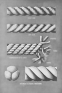
Figure 5-1. Rope lays.
--70--
-
Marline, 2-stranded, left-handed; has the same uses as spun-yarn but is used where neater work
is required.
-
Houseline and roundline, 3-stranded; have same uses as marline. Houseline is left-handed;
roundline is right-handed.
-
Seizing stuff, 3-stranded, right-handed; may have 2, 3, or 4 threads to the strand. It is used where
heavier, stronger, and neater material than any of the preceding cordage is required. Tarred
American hemp is the standard material used in making it.
-
Ratline stuff, 6- to 24-thread, differs from seizing stuff in that it is larger. It is used in making
heavy lashings for spars, anchors, and boats, and to a large extent for heaving lines.
Other small line which is not generally classified as small stuff includes signal halyards, lead lines,
and log lines. These may be either three-stranded or braided cord of cotton, flax, or hemp.
5A5. Uses of rope. Rope has many uses on board ship; some of the most common are: (1) mooring
lines; (2) towing hawsers; (3) halyards, shrouds, and stays; (4) lines for handling heavy weights; (5)
lines for lowering and hoisting boats over the sides; (6) material for constructing fenders; (7) dip ropes
and preventer hawsers; (8) rigging aloft and over the side; and (9) falls and whips for stores and
cargo handling.
5A6. Notes on the care of rope.
-
Care should be taken to prevent kins when new coils of Manila
rope are being uncoiled. To open a coil of rope, first loosen the burlap cover, and lay the coil on the flat
side with the inside fag end nearest the deck. Then reach down through the coil, and draw the rope up and
out of the coil. Newer coils of rope have tags attached to the inside fag end at the front of the coil
bearing the notation "Draw from this end."
-
Do not attempt to put maximum strain on a rope which has seen continuous service under a
moderate strain, nor on one which has been close to the breaking point. The safety of a rope decreases
rapidly with use, depending to some extent upon the amount of strain. This is due to the fact that the
fibers slip a small amount under each strain in spite of the twisting.
-
Taut dry ropes should be immediately slacked off when wet by rain. Rope shrinks in length when
wet, and unless allowed to do so freely, subjects itself to a strain as great as, or greater than it would
carry under load.
-
Great care must be taken to keep rope from contact with acid.
-
Rope should never be put away wet or damp. After use, rope should be cleaned of sand, grit, and
salt water by wetting it down with fresh water before drying. Rope should b e hung up if possible to insure
free circulation of air.
-
Rope should be stored in a dry, well-ventilated place. This will prevent jmildew and dry rot which
greatly decrease the life of the rope.
-
Rope must be gone over at frequent intervals to make sure that no part of it is deteriorating. The
lay should be opened and the inside yarns should be inspected. If the rope is powdery and fibers broken, use
it with care.
-
Standing rigging should be given a treatment of tar oil and coal tar at regular intervals.
This protects the rope and prevents it from deteriorating.
5A7. Size of fiber rope. The size of a fiber rope, except small stuff, is given by its circumference in inches.
It varies in circumference from 3/4 inches to 16 inches.
As a rule, 10-inch rope is the largest standard size issued to the naval service.
The length of rope is expressed in fathoms, and it is issued in coils of from 100 to 200 fathoms.
The size of small stuff is designated by the number of threads it contains, the largest being "24-thread
stuff."
A hawser is any rope 5 inches or more in circumference. Such ropes are used for towing, making fast
to a wharf, or any other kind of duty requiring the use of lines possessing great strength.
5A8. Working rules for lines. To find the safe working load for Manila line, square the circumference in
inches and divide by 7 for the load in tons. In other words, the safe working load for 3-inch Manila line
would be approximately 32 ÷ or 1.3 tons.
To find the size of Manila line for a given load, multiply the load in tons by 7, and take the square root
of the product. The result is the circumference of the line required in inches. In other words, to lift a weight
of 10 tons will require a rope equal in circumference to &sqrt;10x7, or approximately an 8-inch rope.
--71--
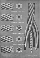
Figure 5-2. Types of wire rope showing cross sections and construction.
--72--
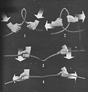
Figure 5-3. The correct way to take a kink out of wire rope--4 steps.
5A9. Wire rope. Wire rope is composed of many wires twisted about a central hemp core, and these
resulting strands again twisted about a central core or heart of hemp. As a rule, 6 strands are used and the
number of wires to a strand varies from 6 to 37. Thus a 6x37 wire rope is made up of 6 strands of 37 wires
each, or a total of 222 wires. The hemp center serves a twofold purpose: first, it acts as a cushion upon which
the strands close in when the rope is caused to contract under a heavy pull; and second, it absorbs some of
the lubricant used on the wire rope from time to time; this results in the almost continuous lubrication of
the interior, and thereby reduces internal friction. Wire rope is approximately three times as strong as Manila
rope of the same size.
A new type of wire rope called spring-lay is now issued for use as mooring lines, and in smaller sizes
for other purposes. It is composed of alternating strands of steel wire and tarred hemp rope, closed in six
major strands around a fiber core, as shown in Figure 5-2.
The remarkable flexibility and elasticity, characteristics
that are frequently very valuable. Spring-lay lines coil easily and lie flat like Manila.
Standing rigging is galvanized to prevent rusting. Galvanizing has not proved practical for wire rope
--73--
 <
<
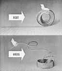
Figure 5-4. The right and wrong way to uncoil wire rope.
which is to be worked over sheaves where great flexibility is desired. Strength is decreased approximately
10 percent by galvanizing.
Some of the common uses of wire rope aboard ship include: (1) mooring lines, (2) standing and running
rigging, (3) towing hawsers, (4) cargo whips, and (5) anchor handling gear.
5A10. Notes on the care of wire rope.
-
Beware of kinks in the handling of lines. A kink will ruin
the best wire rope. For this reason, it should always be stowed on reels, and it should not be removed from
the reel in bights.
-
Sharp bends should be avoided in any type of use. When wire rope is used with sheaves, the
diameter of the sheave should never be less than 20 times as great as the rope in use.
-
When in use, wire rope should be thoroughly and frequently lubricated, preferably with linseed
oil. The lubricant must be thin enough to reach the core.
--74--
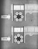
Figure 5-5. The correct and incorrect ways to measure wire rope.
-
Chafing gear should be used where wire rope passes through a chock to prevent wear due to rubbing.
-
When the outside wires are worn to one-half their original diameter, or numerous broken wires
show, wire rope should not be used.
-
Avoid sudden strains when using wire rope. A sudden strain may prove sufficient to snap the rope.
--75--
-
All wire rigging should be inspected at regular intervals and the protective coating of tar oil and
coal tar renewed.

Figure 5-6. Parts of a line.
5A11. Measuring wire rope. The size of wire rope is designated by its diameter in inches across
its widest part. It is well to take at least three measurements at intervals of several feet and strike
and average.
Wire rope may be further classified according to the number of strands and wires, for example
6x12, 6x19, 6x37, etc. This basis of classification has been explained previously.
The length of wire rope is measured in fathoms, as in fiber rope.
B. Marlinespike Seamanship
5B1. Introduction. Marlinespike seamanship is the branch of seamanship which has to do with the art
of knot making, splicing, rigging, and tackles. In the days of sail, every sailor had to be an expert in this
branch. He constantly practiced ropework and gauged the caliber and ability of his shipmates by their
proficiency in handling lines. It is still a tremendously important part of the seaman's profession.
There are literally dozens of knots and splices and while it is not necessary that every naval officer
be able to tie all of them, there are certain common ones used quite frequently aboard ship that he should
know and be able to use. Knots are generally classified as follows:
-
Knots tied with the end of a rope, or a bight, upon its own standing part
(see Figure 5-6).
-
Bends used to secure (bend) two rope ends together. These may be termed either bends or knots;
a square knot is actually a bend.
-
Hitches used to secure a rope, either end or bight, to a hook, ring, spar, or another rope.
5B2. Knots. Square or reef knot. The name of this knot is derived from its being used to tie reef points,
when reefing a sail. It is a most useful knot, a good knot for tying up things such as packages. It can
also be used to bend the ends of two lines of equal size together. It does not jam, and therefore is easily
loosened. The square or reef knot is tied by forming an overhand knot by crossing the ends, and then
bringing one end up through the bight alongside its own part. A beginner may tie a granny knot instead
of a square knot by having one end up and one end down through the bight. The granny is considered
an unseamanlike knot and will work loose under pull.
Bowline. This has been called the "king of knots." Nothing can jam it. If properly made, it will
never slip. It may be used in lowering men over the side, in attaching a painter to a ring, and in forming
a temporary eye in the end of a line. It actually has hundreds of applications.

Figure 5-7. A square or reef knot, and a granny knot.
--76--

Figure 5-8. Steps in forming a bowline.
In making a bowline with gear of moderate size, first form a bight in the line. Grasp the bitter end
in the right hand and the standing part in the left, both palms up, standing part and end leading away
from body. Then place the bitter end over the top of the standing part. Place the index finger of the right
hand on top of this end crossing the bight. Turn the right wrist outboard (i.e., to the right) and you
will form a loop in the bight and, at the same time, have placed the end of the rope upward through this
loop in one motion. This loop is called the gooseneck. Then finish the knot by holding the loop together
with the left hand and carrying the end back around the standing part of the line from the right side and
then down through the gooseneck. This is the sailor's method of casting a bowline in a line.
Bowline on a bight. This knot is well known although it actually has little use. It may be used where
it is necessary to have greater strength than that given by a single bowline, or where the end of the line
is not accessible.
It is formed in the ordinary way except the bight is used instead of the end, all parts being double.
After the bight has been brought up through the gooseneck, it is passed down around the loop and up in
back of the standing part. Figure 5-9
shows how this is done.
5B3. Hitches. Cat's paw. When it is necessary to clap a tackle on a line, or a handy billy on the hauling
part of a larger purchase, a cat's paw may be used.
It is formed by twisting two bights and passing the hook of a tackle through them. This hitch is very
convenient and secure, and assumes a hold for a steady pull.
Two half hitches. This is a very useful knot when making lines fast to spars, bollards, and rings.
It may be formed by leading the end over and under and up alongside the standing part, and repeating
the same operation to form the second hitch.
Round turn and two half hitches. This knot is the same as two half hitches except that an additional
turn is taken around the bollard or spar. The end may be stopped down, thereby making the hitches more secure.

Figure 5-9. A bowline on a bight.
--77--

Figure 5-10. A cat's paw, and two half hitches.
The clove hitch. This is a most convenient knot for making a line fast to a spar, the standing part
of another line, or a bollard. Actually it is two hitches about a spar or larger line. See Figure
5-11 for method of forming.
Rolling hitch. This hitch is very effective when a pull is to be made along the length of a spar. It is
held from slipping by jamming the double turn under the hauling part. See Figure
5-12 for method of forming the rolling hitch.
Blackwall hitch. This hitch is used to secure a line to the hook of a block. Generally, it is better
to form a bowline, unless the end is very short; then the blackwall hitch may be used. Figure
5-13 shows how this hitch is formed.
5B4. Bends. Becket bend.
Sometimes called the sheet bend or halyard bend,
the becket bend is used in bending on flags where hooks are not fitted, and joining two lines,
particularly if they are of different size.
This bend may be formed either single or double. The single becket bend is made by passing the end
of one line up through the bight of another, around both parts, and under its own part. The double becket
bend is similar, except that the bending line is passed twice around the standing line before it is passed
under its own part, thus giving additional security. The ends may be stopped to the standing parts, thus
increasing the becket bend's reliability.
Fishermen's bend. The fishermen's bend is useful for securing a line to a ring, buoy, or the Jew's
harp of an anchor. It is sometimes used to bend a line to a bucket thereby acquiring the name bucket hitch.
It is formed by passing the line twice around the ring and tucking the end under the turns. When its
use is to be of a permanent nature, the end should be stopped to the standing part.
5B5. Splicing. Splicing is a method of permanently joining the ends of two lines or of bending a line back
on itself to form a permanent loop or eye. If properly made, it does not weaken the line, and enables the
line to run over a sheave with greater freedom than if the line contains a knot. Although there are many
splices, we will consider only three types.

Figure 5-11. Round turn and two half hitches, and a clove hitch.
--78--

Figure 5-12. A rolling hitch.

Figure 5-13. Single and double blackwall hitches.
Splicing tools. Every sailor should carry a sharp knife which is quite necessary when working with
lines. Another useful tool is the marlinespike, a pointed steel tool about 1 foot long, approximately an
inch in diameter at the butt, and tapering to a point, It is used to open the strands of a wire rope line in
slicing.
The fid is similar to the marlinespike except that it is larger in size and is generally made of extremely
hard, tough wood, such as lignum vitae or hickory. It is kept very smooth and highly polished. The fid is
used especially in splicing Manila and hemp lines.
Three-strand eye splice. In making this splice, the line is first unload for a sufficient distance from
the end (probably about 1 foot), depending upon the size of the eye wanted. The strands should be of

Figure 5-14. Sheet or becket bend, single and double.
--79--

Figure 5-15. Fishermen's bend, and a fid.
sufficient length to tuck three times. It is well to whipe the ends of the strands of a large line before
beginning to tuck, as this will prevent unraveling.
Next, bring down the crotch of the strands upon the body of the line to form an eye of the desired
size. Lay the strands with the middle one up and one lying on either side, the eye toward you. Tuck as
follows (see Figure 5-16):
Middle strand (a) under the strand immediately below it. Haul firmly tight, tucking from right to left.
Then tuck the left strand (b) under the next strand of the rope from right to left, and haul firmly taut.
Turn the splice over and after giving the remaining strand (c) an extra twist with the lay, tuck it
under the remaining strand from right to left.
Make certain that all 3 strands are hove taut and that the eye is not distorted.
If the splice is to be finished and served, it is customary to cut out a third of the yarns after each tuck.
These are cut out on the underneath part of the strand.
The second and third tucks are made by going over the first strand and under the next. After making
the third tuck, cut off the ends about a quarter of an inch from the rope after first getting the eye on a
good stretch.
It is sometimes a good idea to put on a whipping at the point where the strands begin to unlay, or
at the crotch, before starting the tucks. This prevents the line from unlaying and should be removed when
the splice is completed.
Short splice. In the short splice, two lines are unlaid for a short distance and then married by interlacing
the strands. Therefore, the first step in making a short splice is to unlay the strands for approximately
1 foot from the end of each line. The ends of the strands should be whipped. The rope may be prevented
from unlaying by a whipping at the point at which the strands begin to unlay. In splicing a large line, the

Figure5-16. Steps in making a 3-strand eye splice.
--80--

Figure 5-17. A short splice.
ends should be stopped down on one side, holding them against the line while tucking the other ends.
The ends are tucked similar to the tucking in the eye splice, over and under from right to left (in a
right-handed line). After one side has been tucked, unstop and tuck the remaining ends. Strands may be tapered
as in the eye splice, thereby producing a strong, neat splice. The resulting splice will be thicker than the
original line.This may make it difficult to run the line through a block, or fairlead.
Long splice. In making a long splice, the ropes are unlaid for two or three feet. The ends are
brought together as in making a short splice, with the strands interlacing as is Figure
5-18(1). However,
instead of tucking immediately, the procedure is as follows:
Beginning at the point where the two parts are placed together, unlay one of the strands to the
right, and lay carefully in its place all but the last 5 turns of the corresponding strand from the
left as in

Figure 5-18. A long splice.
--81--

Figure 5-19. The parts of a block.
Figure 5-18(2).
There are still two pairs of strands left at the point where the two parts were brought
together. Run one of these pairs to the left in the same manner as the first pair to the right. Cut the long
strands off about 5 turns from the main rope as in Figure
5-18(3) and
5-18(4). The ends of the three pairs
of strands must now be tucked as in Figures
5-18(5) and
5-18(6), by bringing the strand from the right over
the nearest strand from the left and under the next strand, also giving the strand from the left one tuck.
Each strand should now be given two more tucks, and when all strands have been tucked, the ends are cut
off. The splice may be made smooth by rolling.
C. Handling of Weights
5C1. Types of blocks and block nomenclature. A block is a device consisting of a frame or shell
which supports one or more sheaves or pulleys over which lines are run. Blocks may have wood or metal
frames. The primary purpose of a block is to change the direction of an applied force, and when properly
rigged, to provide mechanical advantages in the application of power to heavy weights.
The four main parts of a block are: (1) the frame, or outside; (2) the sheave, or wheel over which
the rope passes; (3) the pin, or axle on which the sheave turns; and (4) the strap enclosing the frame
by which the block is held together. The frame may be of either wood or metal, the use of metal being
more general. The sheaves, pins, and straps are usually of metal. The sides of the frame are called the
cheeks. The hole through which the rope reeves is called the swallow. The end of the block which is
opposite the swallow is called the breech. The complete outer part is known as the shell.
Blocks are classified according to the number of sheaves as: (1) single, (2) double, or two-fold,
(3) treble, or three-fold, and (4) four-fold.
Blocks may also take their names from their use, some peculiarity in their shape, or from the places
which they occupy. A fiddle block gets its name from its shape; cat and fish blocks from the fact that they
are used to cat and fish an old-fashioned anchor; and gin blocks from the fact that they were originally
attached to gins, which are three-legged, portable hoisting rigs.
The snatch block is perhaps one of the most useful loose blocks found on board ship. This block may
be employed conveniently as a lead block since it is fitted with a hinged shell so that a line may easily
--82--

Figure 5-20. Blocks.
be snatched on the bight. In using this block, care must ber taken that the hinged shell does not open at
the wrong time.
5C2. Tackles and purchases. The terms purchase and tackle (pronounced taykle) are used
synonomously. A purchase consists of a block, or combination of blocks, such as a fixed block which is fastened
to something stationary and a moveable block on the object to be moved, and a fall or falls rove through
the blocks. The part of the fall made fast to the becket of one of the blocks is called the standing part,
and the end to which the force is applied is called the hauling part. A purchase is a mechanical device used
to multiply the effect of force applied to the hauling part of the fall. In other words, the use of a purchase
will enable a pull to be exerted or a weight to be lifted which is several times greater than the force or
weight applied to the end of the rope. The ratio of the force created to the force applied, expressed in
small whole numbers is known as the mechanical advantage of the tackle. The simplest method used to
determine the mechanical advantage of the purchase is to count the number of lines above the movable block.
The following are some of the common tackles used aboard ship:*
-
Single whip. A fixed single block with a line rove through it, the end of which is secured to the
weight to be moved. Since there is no movable block, it does not multiply the force applied, but
does change the direction of the pull and furnish a convenient method of hoisting.
-
Runner. A single movable block which is free to move along a line, one end of which is the
standing part. Its mechanical advantage is 2 to 1.
-
Whip and runner. Two single blocks, one fixed and the other rigged to move along a line, one
end of which is the standing part. Its mechanical advantage is 2 to 1.
-
Gun tackle. Two single blocks, one fixed and movable, the standing and hauling part leading
from the same block. The mechanical advantage is either 2 to 1, or 3 to 1, depending on which
block is attached to the movable object. In the old days, these tackles were used to rains the guns;
hence the name gun tackle.
-
Luff, jigger, or watch tackle. The luff tackle is one of the most useful tackles. It consists of a
single and double block. The standing part of the fall is made fast to the becket of the single
* Throughout this discussion, friction will be disregarded. Actually the mechanical advantage
will be lowered due to friction. In actual practice, the thumb rule used in allowing for friction is to
add ten percent of the weight to itself for each sheave passed over by the falls.
--83--
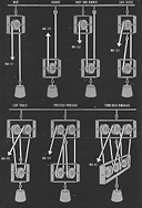
Figure 5-21. Tackles.
--84--
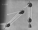
Figure 5-22. Luff upon luff.
block, rove through the double block, back through the single block and back again through the
second sheave of the double block. When the single block is attached to the object to be moved
the mechanical advantage is 3 to 1; when the object to be moved is attached to the double block,
the mechanical advantage is 4 to 1.
-
Two-fold purchase. Two double blocks with the standing part of the line made fast to the becket
of the block from which the hauling part comes. The mechanical advantage may be either 4 to 1,
or 5 to 1, depending upon the block attached to the object to be moved. This purchase is used
for lifeboat falls.
-
Three-fold purchase. Two triple blocks with the standing part of the line made fast to the becket
from which the hauling part comes. This is usually the heaviest tackle found aboard ship. It is
used for handling anchor gear and other heavy weights. The mechanical advantage may be either
6 to 1, or 7 to 1, depending upon which block is attached to the object to be moved.
When reeving tackles, assuming that the line to be rove as a fall is right-handed, the two blocks
to be used are placed on the deck, hooks up. The end which is to be the standing part is led into the
sheave from which it is intended to lead the hauling part, and rove off the tackle from right to left, or
counterclockwise. When the standing part comes to an end, splice or blackwall hitch it into the becket of
the block to which it is to be made fast.
5C3. Rigs and gear for handling heavy weights. There are times when special gear must be rigged
in order to handle extremely heavy weights on shipboard. Although there are many such arrangements,
only a few will be discussed here.
Luff upon luff. It is sometimes a good plan to clap a tackle on the hauling part of another tackle
where great force is required. The theoretical mechanical advantage of such an arrangement is the product
of the mechanical advantages of the separate tackles. The proper method of rigging a luff upon luff is to
bend the double block of one luff to the hauling part of the other luff. Such a method of rigging would
have a mechanical advantage of 12 to 1, or 3x4 to 1.
--85--
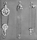
Figure 5-23. Chain hoists.
The simplest manner of attaching a tackle to the hauling part of another is to form a cat's paw or a
blackwall hitch in the hauling part and slip it over the hook of the block.
Chain hoists. The chain hoist is an important part of ship equipment. It is used constantly in the
engine room in lifting heavy parts of machinery and in slinging oil barrels. It is also very useful on deck,
and an officer should become familiar with its application.
Many different designs of chain hoists are on the market. In principle however, they are a combination
of an endless chain, or chains, two or more blocks, and certain gears for the application of forces,
usually applied by a secondary endless hauling chain which transmits the hand pull to the upper block.
By means of such an arrangement, a great weight may be lifted with a small effort. For example, a pull
of only 140 pounds on the hand chain is required to lift 20 tons on one type of chain hoist.
Yard and stay tackles. Yard and stay tackles take their names from their application on ships
with masts and yards, where they were used together for transferring stores from a boat alongside to the
--86--
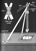
Figure 5-24. Shears for handling heavy weights.
--87--

Figure 5-25. Yard and stay tackles.
deck or hatch of the ship. The general principle involved in the yard and stay is of wide application
on shipboard in cases where a weight is to be lifted and transferred to a point at no great distance. Assuming
two points favorably placed for carrying the upper blocks of the purchases (see Figure
5-25), the weight
is hoisted by the yard tackle (so-called for convenience) to a suitable height, the stay tackle
being left slack. The stay tackle is then hauled taut, and as the yard tackle is eased away, the weight swings
in and hangs by the stay tackle, ready to be lowered away. Modifications, applications, and extensions of
this principle will readily suggest themselves.
Shears. Shears are a convenient device when it is necessary to lift heavy loads in places where nothing
is available to support the tackle to be used. They are constructed simply by lashing two spars together
as in Figure 5-24.
The legs are spread and the heels of the spars stepped into shoes on the deck, and
lashed. Fore and aft guys are rigged which support the shear legs at the desired angle, as nearly upright
as possible. The purchase is secured to a strap passed around the lashing and the weight handled therefrom.
The weight may be moved forward or aft by manipulation of the guys.
Tripod. In cases where the weight is very heavy and need by lifted only in a vertical direction, with no
appreciable fore and aft movement, a tripod can be quickly and conveniently rigged. This is a rig similar
to shears, but with 3 legs instead of 2.
Gin pole,or standing derrick. A gin pole is a single spar with the butt resting in a shoe on deck,
and help upright by 3 or 4 guys running to its top. The tackle is either lashed to the spar or suspended by
a sling run through a slot in the head of the pole. The standing derrick is handled by manipulation of the
guys, or by means of a topping lift led from the head of the spar to a mast.
--88--
Table of Contents *
Previous Chapter (4) *
Next Chapter (6)


 <
<


