Chapter XXIII
Cargo Handling for APAs, AKAs, APs, AKs, XAPs and XAKs

Index

Section 1. Cargo Handling Teams
Section 2. Cargo Handling Rigs
Section 3. Testing Cargo Handling Gear

Section 1. Cargo Handling Teams

  1. In Amphibious Operations it is necessary to handle the Combat Loaded Cargo and the cargo for Garrison Forces under the most difficult unloading conditions by placing it into LSTs, Landing Craft, and Landing Boats alongside ships lying-to or anchored in open roadsteads. Unless this cargo is unloaded expeditiously, it may mean the difference between the success or failure of the Amphibious Operation, and further, it may result in the loss of the Transports or Cargo Vessels themselves.

  2. Combat cargo handling by ships engaged in or supporting, an Amphibious Operation, is a "Military Evolution" which requires trained cargo handling teams just as much as the battery of the vessel requires trained gun crews.

  3. Each APA, AKA, AP and AK of this force having naval crews will organize cargo handling teams composed of Winchmen, Hatch Tenders, and deck Petty Officer Supervisors. The Standard Cargo Handling team based on a five (5) cargo hatch ship will be composed of:

    20 Winchmen
    10 Hatch Tenders
    2 Deck Petty Officers for forward hatch group
    2 Deck Petty Officers for after hatch group
    2 Deck Petty Officers for controlling boats coming alongside

  4. The Commander Operational Training Command, U.S. Pacific Fleet, has set up a Winchmen and Hatch Tender Training School at San Francisco at which school cargo handling teams will be trained.

  5. Cargo Handling teams composed of Naval personnel will be trained by the Winchmen and Hatch Tenders School at San Francisco and set up in a pool from which the cargo handling teams for merchant crew manned XAPs and XAKs will be taken.

  6. As the opportunity for training cargo handling teams is very limited and can only be accomplished during the short periods of Amphibious training and loading and unloading, vessels of this force will take advantage of the training facilities provided by the Winchmen and Hatch tenders School whenever possible.

»XXIII-1«

Section 2. Cargo Handling Rigs

  1. One of the prime missions of Amphibious Force Vessels in Target Areas is the safe and efficient discharge of cargo. In order to obtain the maximum degree of efficiency, it is necessary to have a complete understanding of the various types of rigs that may be employed.

  2. Although Amphibious Force ships vary in type, the gear employed in cargo handling in general follows the same construction principle, therefore, the method used in rigging and cargo handling will not differ to any great extent on the various ships. The following formula and schematic diagrams show the principles involved in the span and must be understood when rigging Yard and Stay.

    1. The Span. Make the angle BOC (page XXIII-4, Fig. 1) as acute (small as practicable. Let B and C (page XXIII-4, Fig. 1) be the point at which the blocks for the span are secured. The falls from the blocks at B and C are joined at O. BW represents the falls from B to W supporting the weight W. Raise the weight W to WL then suppose it is required to have the weight travel the straight line OO'O" until it is hanging vertically from the falls from C. We want to find the forces acting in BO and CO. Since the force W is pulling down, draw the arrow W2 pointing downward. Lay off Oa equal to W to scale (one inch equal W). Draw ab parallel to BO and prolong OC to b, the point of intersection of these two lines. In the triangle Oab draw in the arrows, head to tail, based on the arrow Oa. The direction of the arrow heads (pointing away from O) shows that BO and OC are in tension. By measuring bo and ab to scale, the tension in OC and OB can be found. In this case tension on OB (ab) is 0.86 W and in OC (bo) is 0.39 W. Similarly at O' and O" the tension can be found by drawing force triangles as at O. At O' on the perpendicular bisector of the lines BC, the tension in each fall will be equal to (0.76 W). At O" the tension in O"C is 0.84 W and in BO" is 0.53 W.

    2. If the angle BOC is large (page XXIII-4, Fig. 2) then the forces in BO and OC will be excessive and even dangerous. Suppose B and C are two patent chain falls secured to a frame by beam clamps; that W is 2000 pounds, and due to the small overhead space it will be necessary to raise W close to B before starting to work it over toward C. Two one-ton chain falls are available to use at B and C. At O, (page XXIII-4, Fig. 2), the tension in each fall will be 2.48 W (one inch equal W) or 5960 pounds. This stress exceeds the designated working load (2000 lbs) by 3960 lbs and may cause a hook or a link failure in one of the chain hoists. This dangerous situation can be eliminated by shoving C closer to Bn, then when the weight has been shifted vertically under C, move the chain fall from B to another point to the right of C. Repeat this several times if necessary in order to keep the angle BOC less than 120 degrees, then the stress in either OB or BC can never exceed the weight W.

  3. The Yard and Stay is an example of the span, therefore, it is to be noted that all loads must be kept as low as possible when hoisting. The force diagrams that have been discussed considered the weights as simply hanging

»XXIII-2«

    from the device in question. Attention is directed to the great danger of sudden jerks and the effect of sudden and large changes in the speed of hoisting or lowering weights. If a body that is being hoisted at a uniform speed is suddenly hoisted at a faster speed, we have, in effect increased its weight. Sudden changes in the speed of hoisting or lowering a weight will cause dangerous forces to be introduced into the system at risk of serious casualty.

  1. The methods of rigging for cargo handling most commonly used are as follows:

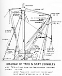
    1. YARD and STAY (see page XXIII-5, Fig. 3). This is the most common method of handling cargo when cargo or vehicles are not in excess of 5 tons. This method has the following advantages:

      1. Allows for the greatest number of lifts per hatch per hour.

      2. Affords better control over the cargo draft or vehicle.

      3. Permits quicker hooking or unhooking of vehicles. This is an important factor when loading or unloading from boats in heavy seas.

        NOTE: Care must be exercised to insure that all loads are kept as low as possible when hoisting with Yard and Stay rig. To determine maximum height that drafts may be lifted, consult the formula contained in paragraph 2308 of this chapter.

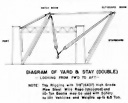
    2. YARD and STAY (double) (see page XXIII-6, Fig. 4). By reeving the whips of the single Yard and Stay through "Runner" blocks at the hook, a double Yard and Stay results. The advantages of this rig are similar to the single rig and may be used to hoist weights or vehicles not in excess of 6.5 tons.

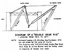
    3. DOUBLE GEAR (See page XXXIII-8, Fig. 6) as shown, consists of "marrying" the falls of two 10-ton booms together. Capable of hoisting weights or vehicles up to 10 tons and with a greater steadying effect than with the swinging boom alone.

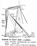
    4. JUMBO GEAR (see page XXIII-7, Fig. 5). This is the swinging boom. It is the heaviest gear on board ship, usually 30-35 ton capacity. Very slow rate of hoist and is normally used for the heaviest lifts.

    5. FRISCO RIG (see page XXIII-9, Fig. 7). This is an emergency rig and is sometimes used on certain type ships where the Jumbo or heavy gear has failed and the cargo or vehicles to be lifted are in excess of the booms remaining at this hatch. The single whips from the outboard and inboard booms are rove through runner blocks at the hook and shackled into whips of the opposite booms and the shackle hauled clear of the runner blocks.

    6. DOUBLE FRISCO RIG (see page XXIII-10, Fig. 8). This is also an emergency rig and may be used where the weights to be hoisted are beyond the safe working load of a single whip.

»XXIII-3«

Figure 1. The Span
Fig. 1

Figure 2.
Fig. 2

»XXIII-4«

Fig. 3 Diagram of Yard & Stay (Single)
Diagram of Yard & Stay (Single)

»XXIII-5«

Fig. 4. Diagram of Yard & Stay (Double)
Diagram of Yard & Stay (Double)

»XXIII-6«

Fig. 5. Diagram of Heavy gear (Jumbo)
Diagram of Heavy Gear (Jumbo)

»XXIII-7«

Fig. 6. Diagram of a Double Gear Rig
Diagram of a "Double Gear Rig"

»XXIII-8«

Fig. 7. Diagram of Frisco Rigging
Diagram of Frisco Rigging

»XXIII-9«

Fig. 8. Diagram of Frisco Rigging (Doubled Up)
Diagram of Frisco Rigging (Doubled Up)

»XXIII-10«

Section 3. Testing Cargo Handling Gear

  1. The increase in the requirements for the handling of heavy loads by means of cargo booms installed on various types of vessels as a result of wartime activities has directed the attention of BuShips to the necessity of insuring the correct methods of designing and testing of such booms and their associated gear are employed.

  2. The attention of all activities concerned has been directed to the following requirements which should be incorporated into the design of cargo booms, running and standing rigging:

    1. A minimum factor of safety of 3-1/2 is required for running rigging.

    2. A minimum factor of safety of 3 is required for standing rigging.

    3. For structural items, including the boom and fittings attached thereto, a minimum factor of safety of 5 on the ultimate strength of the material is required.

    4. A minimum factor of safety of 3 is required for Vangs. This is based on the fact that Vangs must be capable of withstanding the loads imposed when the ship is listed 10 degrees and the boom is in a fore and aft position.

  3. The following tests are required of new shipboard installations:

    1. A load equal to twice the working load shall be hoisted clear of other support and sustained for at least 10 minutes, but need not be rotated.

    2. A load equal to one and one-half times the working load shall be hoisted, rotated, lowered, and stopped at the speeds specified for the installations concerned.

    3. No permanent set shall result from these tests after the initial play and lost motion are taken up by the first application of the load.

  4. In stating the foregoing requirements for testing, no mention was made of the boom angle at which the tests are to be conducted. In general, a boom test angle of about 45 degrees is considered to give a reasonable test of all parts of the rig except that when topping of the boom under load conditions is required, the test should be started at the lowest boom angle required by the design and topped to the 45 degrees required for the remainder of the test.

  5. The tests described above are applicable to all auxiliaries under construction and conversion as well as new or replacement installations on vessels in service. Routine tests of cargo handling gear on vessels in service should also comply with these requirements.

»XXIII-11«

Table of Contents  *  Previous Chapter (22) *  Next Chapter (24)


Transcribed and formatted for HTML by Patrick Clancey, HyperWar Foundation