 |
Restricted
G-93
Depending on the job to be done, several types of projectiles can be fired from the caliber .50 machine gun. But the method of firing the round is the same in all cases.
The primer consists of a brass cup, a highly explosive primer charge, a shellacked paper disk to keep out moisture, and a brass anvil with a pointed end.
The primer fits into a circular primer pocket in the base of the cartridge case. The front edge of the case is bent into a groove, or cannelure, in the side of the bullet to hold it in place.
When the gun's firing pin dents the primer cup, the primer charge, squeezed between the cup and anvil, explodes.
Flame flashes around the anvil and through a vent in the cartridge case, setting fire to the propelling charge, a quantity of black, smokeless powder loosely packed in the case. The propelling charge does not explode all at once, but burns steadily from back to front in a fraction of a second. Gases given off by this burning create the chamber pressure of about 50,000 pounds to a square inch. The case is forced against the sides of the chamber, and the projectile is blown forward out of the case and through the barrel.
Types of Ammunition The types of ammunition used by aerial gunners can be identified by colors painted on the tips of the bullets. The chart on the next page shows the kinds of ammunition, and the use, identification, and construction of each type.
Restricted
G-94
| TYPE | USE | COLOR OF TIPS | HOW IT WORKS |
|
|  | ||
| Ball (Cartridge, ball, caliber .50, M2) | Used against personnel and light material targets | Unpainted, plain copper color |
A jacket of copper-colored gilding metal encloses the steel core.
A lead and antimony point filler fills up the space between the core and
the jacket. When the projectile hits a target, the soft jacket smears, giving the steel core a grip. The core penetrates the surface instead of being turned aside. |
|
Armor-piercing | Used against armored aircraft and vehicles, concrete shelters, and other bullet-resisting targets | Black | The projectile is the same as a ball cartridge, except that the core is made of a very hard tungsten chrome steel to give it greater penetrating power. |
|
|  | ||
|
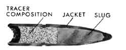
Tracer | Used for observing fire— it makes a streak of light easily seen at night, and usually visible in daylight. | Red | Inside the gilding metal jacket is a slug of lead and antimony. Behind it is a packet of tracer composition which is set afire by the propelling charge as the projectile leaves the cartridge case. |
|
Incendiary | Used to set fire to ex-plosive or very inflammable targets, like gasoline tanks and balloons. | Light blue | In the front of the jacket is an incendiary composition. It is sealed by plugs of an alloy which melts easily. As the bullet goes through the barrel, the heat melts the plugs. The incendiary composition is et on fire when the air touches it. |
|
Dummy | Used in training. | Unpainted (Hole in side of case) | A round with no priming charge and no propelling charge. A hole is drilled in the side of the case. |
|
Armor-piercing | To set
fire to armor- plated inflammable objects, such as the gas tanks of fighter planes. | Black, with a small blue tip on the nose | Similar in construction to armor-piercing projectiles, except that there is incendiary compound behind the steel core. |
Restricted
G-95
Colored ink marking
Another kind of marking sometimes is used in target practice. The tips of the bullets are painted in lithographic ink, which leaves colored smears when the bullet hits the target. When several gunners fire at the same target, a different color is assigned to each gunner. The scores can be determined by counting the colored smears on the target.Care and Handling
Ammunition which is carelessly stored or handled soon develops defects which may stop your gun in the midst of an attack. These tips are worth remembering:
Since small arms ammunition deteriorates quickly when exposed to the direct rays of the sun, it should be stored indoors whenever possible.If it must be stored in the open, the boxes should be raised on blocks at least six inches above the ground, and covered with a double thickness of tarpaulin draped in such a manner that air can circulate freely through the pile. Dig a trench around the pile to keep water out. Don't remove ammunition from its airtight packing boxes until it is needed—it corrodes rapidly, especially in damp climates.
These storage precautions apply especially to tracer ammunition, which deteriorates quickly when it becomes damp, and may go off spontaneously if it gets too warm. Tracer should be stored separately from other ammunition if possible.
Keep the cartridges free of mud, sand, dirt, and water. If they do get dirty, wipe them off at once.
Never use grease or oil on ammunition. Small arms ammunition will not explode violently if it is in a fire. But each cartridge will explode individually, sending the case flying in one direction and the projectile in another. Unless you are engaged in fighting the fire, don't stand near it.
Checking Ammunition
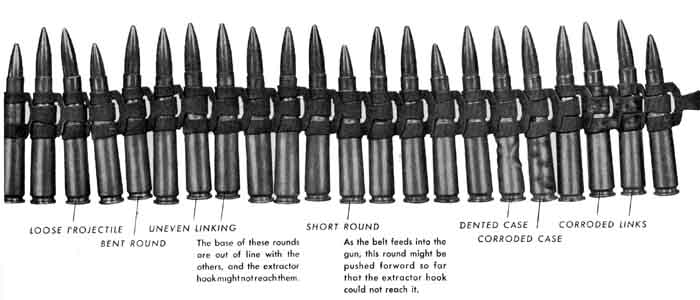
To avoid stoppages in combat, check your ammunition carefully before loading it into the ammunition can of your bomber, unless you are absolutely sure it has already been checked by ordnance.If a clean, dry floor is available, lay the belt out in a long row and examine it carefully. If the only space available is muddy or greasy, check your ammunition by loading it, double-end first, into a box. Then load it into your ammunition can, single-end first, watching for defective rounds as you pull the belt toward you. You will probably never see a belt of ammunition this bad, but the picture shows what you should watch for while checking ammunition. Remove any defective rounds.
Restricted
G-96
| In the bomber, ammunition for hand-held guns is carried in steel or wooden containers, usually mounted above or to the side of the gun position. The ammunition belt feeds out the top of the container, over a roller, and through a flexible feed chute attached to the gun. | |
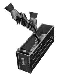 | Load the ammunition into the container with the single end of the links going in first, so that the double end will go into the gun. Put the rounds in the container in even layers, checking for defective cartridges as you go. |
| Mount the container in the bomber, with its roller toward the gun. Methods of mounting the container vary in different planes and different combat theaters—it may sit on the floor, or be fastened into a rack with clamps, pins, or straps. | |
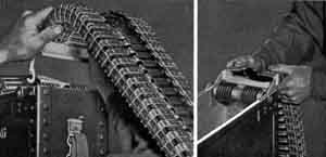 | |
| Attach the feed chute to the container, open side up, by pushing its two hooks into the slots in the sides of the container and pulling them under the pin that holds the roller. (In some cases, pins or clamps are used to fasten the chute.) | |
| Mount
a feed chute adapter on the gun on the same side as the belt holding pawl. Remove the belt holding pawl pin, straddle the belt holding pawl with the projections of the feed chute adapter, and replace the pin. On the same side as the belt holding pawl. Remove the belt holding pawl pin, straddle the belt holding pawl with the projections of the feed chute adapter, and replace the pin. | |
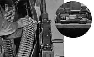 | |
| Attach the feed chute to the adapter. Squeeze the two handles on the bottom of the flexible feed chute—this will open a slot in the front of the chute. | |
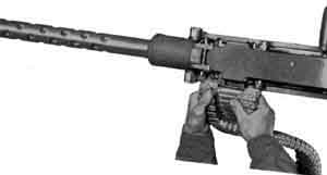 | |
| Push the slot down over the T-shaped wings of the adapter and release the handles. Feed the end of the ammunition belt over the roller and into the top of the chute, and pull it down to the gun. Load the end of the belt into the feed-way in the usual manner. | |
Restricted
G-97
Thorough care and inspection of your gun before and after every mission are your insurance that the gun will always start firing when you want it to, and keep on firing. The inspections take time, and they are worth every minute of it. Gunnery officers in some theaters, for example, try to allow a full hour for the preflight check and two hours for post-flight. Follow this check list. Never omit a single step. Leaving out a single check, just one time, may cause the loss of an airplane—plus the crew.
| PRE-FLIGHT CHECK LIST | |||
| Before assembling gun . . . | |||
| 1 | Check the T-slot for burrs. | On the adapter . . . | |
| 2 | Check the recesses in back of the bolt, firing pin port, and driving spring hole for dirt, excessive oil,or fouling. | 12 | For the Mk 6 Mod 3 and Mk 10 adapters check the oil leveling the hydraulic units. |
| 3 | Check the oil level in the oil buffer tube. | 13 | Mount the gun in the adapter and check for proper mounting and safety wiring. |
| 4 | Check the bore and chamber for dirt of excess oil. Pull a clean, dry rag through the barrel. | 14 | Before loading the gun, hand-charge the gun in the adapter, testing for smooth operation and firing. |
| 5 | Check the receiver to see that the extractor switch and its spring, the belt holding pawl, and cartridge stops are clean and correctly assembled | 15 | Charge three of four rounds through the gun to check the feeding mechanism. (Be sure the safety is in the SAFE position. Don't feed ammunition into the gun while it is in stowed position, pointed at any part of the ship, or aimed in any direction that might endanger personnel or equipment on the field. |
| After assembling the gun . . . | 16 | Clear the gun, raising the cover to make sure the feedway and chamber are empty. | |
| 6 | Check the bolt switch, belt feed slide, and cartridge stops for direction of feed. | 17 | Check the sights to make sure they are not loose or damaged. (The preflight checks for optical and computing sights are listed in the sight section) |
| 7 | Check the operation of the cover latch and detent pawl. | 18 | If ordnance does not do it, check your ammunition for corroded, dented, or bulged cases; short rounds, incorrect linking, and bent or rusty links. |
| 8 | Check all cotter pins (especially those on the extractor switch and belt feed lever) | And finally ... | |
| 9 | Check the safety wiring on the retracting slide | 19 | If cooperating policy permits, take along a screwdriver and combination tool, one complete spare bolt group, and as many other spare parts as possible. |
| 10 | Check the four adjustments: buffer adjusting screw, oil buffer, headspace, timing. | 20 | When a new gun is issued to you, test-fire at least 75 rounds before using it on a mission. |
| 11 | Hand-charge
the gun, testing it for smooth operation and correct action of the firing mechanism | ||
Restricted
G-98
| Post-FLIGHT CHECK LIST | |||
| 1 | First make sure the chamber is empty. | In the bolt group . . . | |
| 2 | Before leaving the ship, check for any damage to the feed chute or ammunition box. | 20 | Check for scoring or burring of the bottom of the bolt body caused by a jittery accelerator. |
| 3 | Report all malfunctions, give the cause if possible, and make sure they are corrected. | 21 | Check for burrs on the T-slot. |
| 4 | Thoroughly clean and oil the gun. As you reassemble the gun, check it part by part, group by group, always in the same order. Usually there will be a spring chart available. Compare the springs with the chart. If you find a spring shorter than the chart shows, it is weak—replace it. To check parts such as the sear notch for wear, compare them with new parts. After cleaning, as you assemble the gun, make the following checks: | 22 | Check
for burrs at the front of the breech block. |
| 23 | Check
for wear on the guides that run in the slots inside the barrel extension. | ||
| 24 | Check
for burrs on the front of the breech lock recess. | ||
| 25 | Check the extractor stop pin for wear and looseness | ||
| In the receiver . . .: | 26 | Check for dirt or primer salts in the T-slot, firing pin port, driving spring hole, breech lock recess and the recesses in back of the bolt. | |
| 5 | Check for adjustment of the breech lock cam, burrs on the cam, or dirt under the cam. | 27 | Check for worn or burred notches on firing pin and sear. |
| 6 | Check for burrs at the rear end of the extractor switch, rust or primer salts on the switch spring, dirt or deposits in the switch recess in the side plate, new cotter pin, operation of the switch after installing it. | 28 | Check
for weak sear spring. |
| 29 | Check for bent worn, or broken cocking lever. | ||
| 7 | Check for weak belt holding pawl spring and worn belt holding pawl. | 30 | Check for worn hook or lug on extractor and bent or broken extractor or ejector. |
| 8 | Check the safety wiring on the retracting slide | 31 | Check for weak ejector spring. (If the ejector pin is staked, test the operation of the ejector with your fingers without stripping it.) |
| In the barrel group . . . | 32 | Check for worn or bent bolt stud. | |
| 9 | Check bearing surface for dirt of corrosion. | 33 | At
regular intervals, as specified by your group ordnance officer, have ordnance
replace the driving spring and firing pin spring. Manufac- turers suggest this be done every 1,000 rounds. |
| 10 | Check
the bore and chamber for wear or damage. | 33 | In the cover group . . . |
| 11 | Check
for burrs on the barrel extension shank. | 34 | Check for burred extractor cam. |
| 12 | Check
for burrs or wear at the top and bottom front edges of breech block. | 35 | Check for weak belt feed pawl spring. |
| In
the oil buffer group . . . | 36 | Check for burred or worn belt feed, pal, pawl arm, or belt feed slide. | |
| 13 | Check
for burrs where the front end of the oil buffer body hits the breech lock cam. | 37 | Check for bent or worn belt feed lever, especially the plug, and for worn pivot stud. |
| 14 | Check
for looseness or wear of the breech lock depressors. | 38 | Check operation of the lever plunger spring. |
| 15 | Check
the action of the tube lock on accelerator. | 39 | Check
operation of the cover latch and detent pawl. |
| 16 | Check
for wear of the accelerator tips. | In the back plate group . . . | |
| 17 | Refill
oil buffer tube. If it takes a large amount of oil, have ordnance check it for
leakage. | 40 | Check the buffer adjusting screw adjustment. |
| 18 | Check
for adjustment of the oil buffer. | 41 |
Check operation of the latch and latch lock. |
| 19 | At
regular intervals, as specified by your group ordnance officer, have ordnance
change the oil in the oil buffer tube and check the oil buffer spring, relief
valve, and packing gland. |
With the gun assembled . . . | |
| 42 | Check the headspace and timing |
Restricted
G-99
| If a gun is carefully cleaned, inspected,
and oiled every day, there is hardly one chance in a thousand that anything will
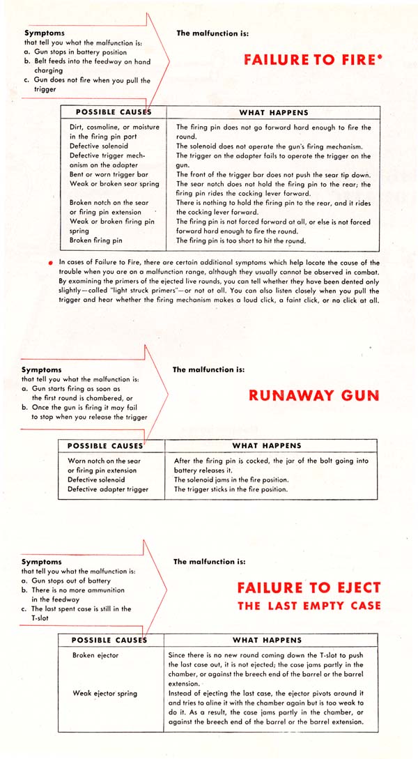
go wrong with it in combat. Reports on gun breakdowns in combat theaters show that nine-tenths are caused by dirty guns, bad adjustments, or other varieties of pure carelessness. Most of the remaining one-tenth could have been prevented by a good preflight check. But if something should go wrong with your gun, the trouble-shooting charts on these two pages show the most practical way of finding out what is wrong and the possible causes of the trouble. To complete your working knowledge of malfunctions—failures—the charts on the following two pages tell exactly what happens inside the gun in each case. | If
the Rate of Fire is too rapid And there is excessive vibration the trouble probably is: Insufficient oil in the oil buffer. | |
| If the Rate of Fire is too slow Or if the gun fires a few rounds and stops, the trouble probably is: Tight headspace Oil buffer adjustment too far toward the closed position, or Too much weight on the ammunition belt. | ||
| If the
gun won't start firing in extremely cold temperatures, pull the charging handle back, hold the trigger down, and release the charging handle. |
If your gun won't stop firing
Restricted
G-100
If your gun stops firing
Restricted
G-101
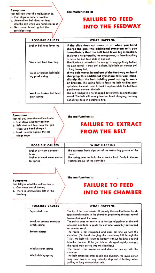
Restricted
G-102
Restricted
G-103
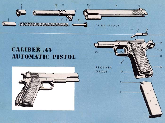
| Nomenclature | ||
| 1. MAGAZINE | 9. BARREL BUSHING | 17. RECEIVER |
| 2. MAGAZINE FOLLOWER | 10. BARREL | 18. SAFETY LOCK |
| 3. MAGAZINE CATCH | 11. BARREL LOCKING NOTCHES | 19. HAMMER |
| 4. RECOIL: SPRING PLUG | 12. BARREL LINK | 20. MAINSPRING HOUSING |
| 5. SLIDE STOP | 13. BARREL LINK PIN | 21. GRIP SAFETY |
| 6. SLIDE STOP PIN | 14. SLIDE | 22. TRIGGER |
| 7. RECOIL SPRING | 15. FRONT SIGHT | 23. TRIGGER GUARD |
| 8. RECOIL SPRING GUIDE | 16. REAR SIGHT | 24. EJECTOR |
|
The caliber .45 automatic pistol is a sidearm often issued to Navy aircrewmen. It is actually a semi-automatic weapon; it loads and cocks itself, but the trigger must be squeezed for each shot. It is simply constructed and light in weight; it can be stripped very quickly without a tool under combat conditions. Yet it will drop a man if the bullet hits any part of his body. At 250 yards, it will penetrate four inches of white pine—and a one-inch penetration is equivalent to a dangerous wound. Its maximum range is about 1,600 yards, its muzzle velocity about 800 feet a second. However, its maximum accurate range is within 100 yards; hits beyond that range are usually more luck than skill. There are two models, the Ml 911 and Ml 911A1, On the Ml 911A1, which is newer, there are slight changes in the shape of the grip safety, trigger, mainspring housing, front sight, and hammer tip. |
Restricted
G-104
STRIPPING
Remove the magazine (1)
by pressing the magazine catch (3) just behind the trigger on the left side.Remove the recoil spring plug (4).
Push in the checkered front of the plug. Then, holding your thumb in front of the plug to keep it from springing out, give the barrel bushing (9) a quarter turn in a clockwise direction. Let the plug come out slowly against your thumb.Take plug off recoil spring (7),
turning it slightly in a clockwise direction if it sticks.Remove the slide stop (5).
Cock the hammer and hold the gun with the left side up. Press in on the slide stop pin (6) with your right forefinger and pull the slide back with your left hand. The slide stop will disengage as the small notch on the slide passes over it. Lift it out the left side of the gun.Remove the slide group
by turning the pistol upside down and pulling the slide forward off receiver.Remove recoil spring (7) and spring guide (8).
Hold the slide upside down and pull the spring back and out.
Restricted
G-105
 |
Remove
the barrel bushing (9). |
 | Remove
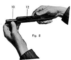
the barrel (10) and barrel link (12) by pulling them forward out of the slide after turning the link forward. The barrel link can be separated from the barrel by drifting out the barrel link pin. |
STRIPPING
Replace the barrel. Hold the slide upside down. Insert the barrel from the front with the barrel link going in first. The link must be turned forward. (See fig. 8)
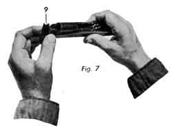
Replace the barrel bushing. Line up the ridge on the side of the bushing with the space between the barrel and recoil spring housing. Push the bushing all the way in and turn it clockwise as far as it will go. (See fig. 7)
Replace the recoil spring and spring guide. Keeping the slide upside down, push the spring into its housing from the rear. The spring guide goes toward the rear with the rounded slot resting over the barrel. (See fig. 6)
Assemble the slide and the receiver. With the slide still upside down, cock the hammer of the receiver, then turn the receiver upside down and push it forward on the slide as far as it will go. Make such the barrel link is tilted forward. (See fig. 5)
Insert the slide stop pin. Hold the gun with the muzzle end of the barrel tilted up and push the slide back until its rear end is just over the hammer. Move the barrel in or out until the hole in the barrel link lines up with the hole for the slide stop pin. Push in the pin as far as it will go. Move the slide farther back, pushing the rear of the slide stop inward and upward to force it in place.
Insert the recoil spring plug. Move the slide all the way forward, leaving the hammer cocked and locking the safety lock. Set the recoil spring plug over the end of the spring (see fig. 3) and push the plug in until it is flush with the slide. Then turn the barrel bushing down until the plug snaps forward between the lips of the barrel bushing. (See fig. 2)
Insert the magazine and push it in until it catches. (See fig. 1)
Restricted
G-106
LOADING
THE MAGAZINE
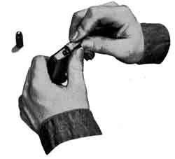 |
To load the first round into the magazine, press the rear of the round down against the front of the magazine follower—the flat metal surface under spring tension—and push the round all the way to the rear. |
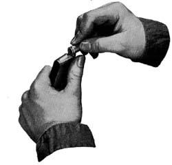 | To load the remaining rounds, hold one thumb beside the magazine as a guide. With your other thumb, press the base of the next round down against the front of the cartridge case of the round already in the magazine and slide it all the way back. |
LOADING THE PISTOL
SAFETY DEVICESAfter seven cartridges have been placed in the magazine, insert the magazine in the receiver. Pull the slide to the rear and let it go forward. (If the slide was already at the rear when the magazine was inserted, press down the slide stop to let it snap forward.)
The pistol is now cocked. Unless you plan to start firing immediately, put the safety lock in safety position as far up as it can be moved.
Eight cartridges can be loaded in the pistol when desired.
Before inserting the magazine draw back the slide, place an extra round in the chamber, release the slide, and put the safety lock
on safety. Then insert the loaded magazine.
Four safety devices prevent accidental discharge of the pistol.
1 The safety lock. The trigger cannot be pulled when the safety lock is in safety position. Before firing, the safety lock must be moved down.
2 The grip safety. The trigger cannot be pulled unless the grip safety is squeezed forward.
3 The disconnector. This is a moving part inside the receiver that prevents the pistol from firing unless the slide is fully forward in battery position.
4 The half-cock notch. If the hammer is not forced back far enough to engage its firing notch, it is stopped by the half-cock notch, which prevents it from slipping forward and firing the round. The trigger cannot be pulled when the hammer is on half-cock. To release the hammer without firing the round, pull it all the way back and allow it to go slowly forward to the uncocked position while squeezing the trigger and grip safety.
Restricted
G - 107
How it Works
 | |
| RECOIL | 1. When the pistol is in battery, the slide and barrel are locked together by the |
| locking notches. As the round is fired, the explosion drives the bullet forward, and also starts recoil. Shortly after recoil starts, the barrel link pivots downward around the slide stop pin. This pulls the rear of the barrel down, separating the locking notches and leaving the slide free to travel farther back. The barrel cannot travel farther back because the barrel link is held by the slide stop pin. As the slide moves back, the extractor—near the rear of the slide group—pulls the empty case from the chamber. The case hits the fixed ejector on the upper left side of the receiver, which flips the case up and out to the right. | |
| 2. As the chamber moves over the magazine, the magazine follower, pressed | |
| upward by the magazine spring, forces the next round partly up into the chamber. (If the magazine is empty, the magazine follower forces the slide stop upward, locking the slide back at full recoil.) The recoiling slide turns the hammer backward, forcing the hammer strut down and compressing the mainspring. Since the bottom of the sear is always being pressed forward by the long leaf of the sear spring, the upper tip is pivoted backward and sticks into the firing notch on the hammer. This locks the hammer back in cocked position against the pressure of the mainspring. | |
 | |
| COUNTER RECOIL | 3. The recoil spring, which is compressed as the slide recoils, now forces the |
| slide forward. The slide hits the new round, which is guided into the chamber by the lips of the magazine and the loading ramp at the breech end of the barrel. Farther forward, the slide hits the rear of the barrel and forces it forward. The barrel link pivots upward around the slide stop pin, forcing the rear of the barrel up into the locking notches of the slide to lock the slide and barrel together. | |
| FIRING | 4. When the trigger is squeezed, the trigger yoke presses the disconnector |
| back against the bottom of the sear, pivoting the upper tip of the sear forward out of the firing notch on the hammer. The hammer, forced forward by the mainspring, drives the firing pin into the primer. The firing pin spring forces the pin back into position. | |
CARE AND CLEANING
| After
a pistol has been fired, it must be field stripped for proper cleaning. With a
cleaning rod and cloth patches, clean the bore and chamber in the same way a caliber
.50 barrel is cleaned. Then saturate a clean flannel patch with light lubricating
oil and swab the bore and chamber. Wipe the exposed working surfaces with an oily
rag. Put a few drops of oil into the openings around the hammer and trigger—it
will work into the mechanism. To clean a pistol which has not been fired, rub the outside with a lightly oiled rag and then with a perfectly dry one. Swab the bore and chamber with an oily flannel patch and wipe off the oil with a perfectly dry patch. Use a small, clean brush to dust out all crevices. If the pistol is to be stored, do not use a cover or place plugs in the chamber and bore—they will cause sweating and promote rust. Because leather absorbs moisture even when it looks dry, pistols should not be stored in holsters. |
Restricted
G-108
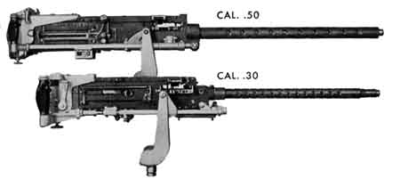 | . . . You Will Use It in Practice The caliber .30, no longer used in aerial combat except on some Navy planes, still is standard equipment for range practice because it uses smaller ammunition. Its operation and care are almost like the caliber .50. The only differences which must be known to use, clean, and adjust the gun are illustrated on the next pages. |
| DIFFERENCES
IN PERFORMANCE | CALIBER .50 | CALIBER .30 |
| Weight | 64 pounds | 20 pounds |
| Rate of fire per minute | 750-850 rounds | 1,350 rounds (approx.) |
| Muzzle velocity
(at 78 feet from muzzle, with A.P. M2) | 2,900 feet per sec. | 2,715 feet per sec. |
| Chamber pressure per sq. in. | 50,000 to 52,000 pounds | 48,000 to 50,000 pounds |
| Maximum range A.P. M2 | 7,200 yards | 4,500 yards |
DIFFERENCES
IN CONSTRUCTION CALIBER
.50 CALIBER
.30 Back Plate Group Trigger
always near the top of the back plate Trigger
below the buffer tube with Mk 12 Adapter. Back
Plate Group Ejector
pivots- to the rear as well as sideways Ejector
pivots sideways only. In changing
the direction of feed, the ejector must
be
placed on the side of the extractor assembly where it will be on the same
side of the ammunition as the cartridge stops.Extractor
assembly guided by a lug which rides over the extractor switch on recoil and under
it on counter recoil. Extractor
assembly guided by a plunger and spring which ride along the side of the extractor
feed cam on recoil, then spring out and ride under it on counter recoil. Both
ends of the bolt stud same length. Two-piece firing pin assembly—one notch.
Vertical sear held by a sear slide. Long
end of the bolt stud goes into the bolt. One-piece firing pin—two notches.
Horizontal sear held by a sear holder, with a plunger and plunger spring. Double
driving spring. Single
driving spring
Restricted
G-109
| CALIBER .50 | CALIBER .30 |
| Oil Buffer Group — Lockframe Group | |
| Removable breech lock depressors. | Breech lock depressors are a fixed part of the lockframe body. |
| Shoulders
of the oil buffer body stop the accelerator. | An accelerator stop pin stops the accelerator. |
| Barrel's
recoil absorbed by the oil buffer and oil buffer spring. | Barrel's recoil absorbed only by the barrel plunger spring. |
| Trigger
bar and trigger bar pin are in the casing group. | Trigger bar, trigger bar pin, and trigger bar spring are in the lockframe group. |
| Barrel Group | |
| Eight lands and eight grooves. Barrel has narrow, V-shaped locking notches; head of the barrel locking spring is pointed. | Four lands and four grooves. Barrel has square locking notches; the barrel locking spring is square-headed. The barrel plunger stud compresses the barrel plunger spring. |
| Barrel extension shank and hook connect the barrel group with the oil buffer. | The barrel extension T-lug is a locking surface for the accelerator. |
| Cover Group | |
|
| Same as caliber .50 |
| Retracting Slide Group | |
| Grip and lever to provide leverage. | Handle , but no lever |
| Cover Group | |
| One-piece front barrel bearing. | Front barrel bearing assembly, which increases the recoil force by letting some of the expanding gases push back on the muzzle of the barrel. |
| For right feed, front and rear cartridge stops and a link stripper are used; for left feed, a front cartridge stop and a right-hand rear cartridge stop assembly.. | For either right or left feed, only front and rear cartridge stops are used; rear stop acts as a link stripper. |
| Extractor
switch guides the lug on the extractor assembly. | Extractor feed cam guides the plunger and plunger spring on the extractor assembly. |
|
DIFFERENCE IN HEADSPACE ADJUSTMENT | |
| After field stripping the caliber .30, remove the nose of the barrel locking spring from the barrel locking notch and move it to one side, letting it rest on the barrel extension. Put the bolt, with the extractor assembly removed, on the barrel extension, push it all the way forward, turn the parts upside down, and hold the breech lock down in its recess with your thumb. Screw the barrel in until you feel the breech end hits the lips of T-slot. Unscrew the barrel just enough to seat the barrel locking spring in the nearest notch. | |
Restricted
G-110