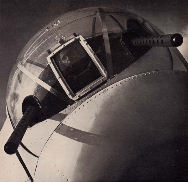
POWER TURRETS

How to operate and take care of them
Restricted
T-1
| Thanks to the Turret . . . | |
| THE BOMBER FIGHTS BACK | |
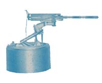
• Without the men who invented the turret, today's great bombing missions would be impossible. For without turrets, the bomber would be almost as helpless over enemy territory as an ordinary transport plane without a single gun. • No one knows exactly who should get credit for inventing the modern turret. The first crude models came out in the 1920's. One was a circular mount, illustrated on this page, which the United States developed to put a little flexibility into bomber guns. The Russians tried a movable platform, cranked by hand, in which the gunner sat right out in the open, fighting the slipstream as well as the enemy. • The modern power turret—driven by electricity and mounted inside the bomber—was developed after many experiments in the 1930's and proved its worth in action in the second year of World War II. Its effect on air strategy was spectacular. At last the bomber—heavier and slower than the fighter plane-could really fight back. • For turrets—little blisters of plexiglas or safety glass, bristling with caliber .50s, swinging around to meet enemy fighters no matter where they come from—enable the bomber to match the enemy slug for slug in an air battle. | |
 | • Approach an American bomber today, from any angle, and you will see a turret whose guns could be turned toward you in an instant. • The top turret swings in a full circle; its guns move up and down from straight out to nearly straight up; it protects the whole top of the plane. • The lower ball turret swings in a full circle and points its guns anywhere from straight out to straight down; it can fight off any attacker who comes from below. The tail turret throws |
Restricted
T-2
out a big cone of fire toward the rear, and the nose or chin turret a heavy cone of fire straight ahead. • Along with hand-held guns sticking out the waist windows and the radio position, the turrets cover almost every square inch of sky around the bomber. No matter where the enemy fighter comes from, he must take his chances with a hail of caliber .50 bullets • The turrets are spun around, and the guns raised and lowered, by electric motors or by hydraulic pressure systems run by electric motors. (In the language of turrets, swinging from side to side is called moving in azimuth; up and down movement is called elevation.) All the gunner has to do is hold on to the control handles of his guns and move them to steer the turret; the mechanism does the rest. • Inside the turret is everything the gunner needs for combat, arranged so that he can get at it in an instant. No space is wasted; although turrets are small, they have everything it takes to fight the enemy. • As a turret gunner—no matter which turret you are assigned to—you will ride into combat seated in back of caliber .50 machine guns and a sight. Often your seat and footrests will be adjustable; if so, learn to use the adjustments properly and you will find them a great aid to both your comfort and your efficiency. • Armor plate or bulletproof glass will protect you as much as possible—though your best defense, like a good boxer's, will still be the offensive power packed by those caliber .50s. • Your guns will be equipped with a special charging system —usually a pulley and cable—which makes it easy to hand charge them in the crowded space of the turret. The guns will be mounted in adapters which cushion their recoil. You will fire them by pressing triggers, usually under your index fingers on the control handles, which release the firing pins by means of electrical devices called ELECTRIC TRIGGERS. •
Ammunition for the guns—enough to carry you through any mission if you don't
waste it—will ride in cans mounted so that the belt runs smoothly into the
feedways. Often BOOSTER
MOTORS will help lift the belt to the guns. And often the | 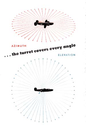 |
Restricted
T-3
empty cases will drop through special EJECTION CHUTES out of the turret or into SPENT ROUND BAGS attached to the ends of the chutes. •
As you swing the guns around, you won't have to worry about shooting at parts
of your own bomber. Every turret where this danger exists has a system of FIRE
INTERRUPTION, or FIRE
CUTOFF, which stops the guns automatically when they are pointed
toward any part of the bomber. | |
| . . . the controls are in easy reach . . . once you have developed the touch, the turret practically runs itself | • Nor will you have to worry about swinging the guns so far that they bang into your own ship. Turrets have LIMIT STOPS which prevent that. On some turrets the limit stops are simply bumpers; others, in addition, have automatic switches which halt the turret before any damage can be done. •All the switches you need to operate the turret will be located within easy reach. The control handles will enable you to run the turret as easily as an automobile. Once you have developed the touch—the secret is to keep a steady hand, without jerking—you will be able to track the enemy smoothly and accurately. • For whirling around quickly to meet a new attack, your turret will be able to get up to high speed. The distance you move the control handles will determine the speed—and in some turrets you will have a special high speed button which throws the turret into high gear to give you an extra boost. If your turret has a high speed button, use it only when you really need it—to avoid unnecessary wear and tear on the power system. • If the turret power should ever fail, you will usually have a MANUAL SYSTEM for operating it by hand cranks. Some turrets even have foot pedals which enable you to fire the guns while using both hands to crank the turret into position. This is an important emergency protection,- use it to keep your guns pointed at enemy fighters even though your fire cannot possibly be so accurate as when the power is on, for a motionless turret is an invitation for fighters to attack. • Even if the
guns are out of order, keep tracking the enemy; if you can't hit him, you may
at least scare him away. |
Restricted
T-4
| The Auxiliary Units |
|
| . . . they are designed for living five miles up |
The manual system for operating the turret is one of the auxiliary units, which are like an automobile's accessories. Without the auxiliary units, the turret and guns would still operate, but the gunner himself would have a tough time of it. For one thing, you can't go five miles up in the sky—which is where you will do most of your fighting —without special equipment for breathing in the thin air and keeping warm in temperatures that range down to 50 degrees below zero. Your turret has that equipment, as well as other auxiliary units for keeping in touch with other crew members, making emergency repairs in the dark, and taking training or combat films. The manual system differs from turret to turret and will be discussed separately in the descriptions of individual turrets. But all other auxiliary units are basically alike, regardless of what turret you use. |
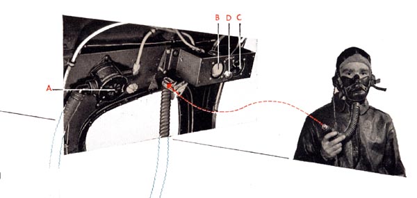 |
1 The Oxygen System Over 10,000 feet, the air gets so thin that a man's efficiency falls off rapidly; he can neither move nor think with any speed. At 25,000 feet, where heavy bombers usually fly, no man can stay conscious without extra oxygen. Your oxygen supply, therefore, is your most important auxiliary unit. You will have a mask connected by a large flexible hose to a regulator (A) which adjusts the flow of oxygen to the amount required at various altitudes. In most turrets, the regulator will be the new demand type, which operates automatically and will always make sure that you get exactly the right amount, no more and no less. There will also be a flow and pressure gage (B, C) which shows whether oxygen is flowing and how the supply is holding up. If the pressure goes down to 100 pounds—the danger level—a warning light (D) will flash on. The source of oxygen supply will depend on the turret. In most turrets, the oxygen comes directly by tubing from the bomber's central tanks. In some, you will have one or two bottles which contain enough oxygen for about one and one half hours, and can then be refilled from the central supply. Before each mission, check all the connections on the oxygen system, particularly swivel joints, |
Restricted
T-5
| to make sure they are tight. Check the hose to make sure there are no cracks or leaks. Then put on your oxygen mask, connect it, and make sure oxygen flows into it—take a look at the flow gage. Check the pressure to make sure it is up to the point required for the mission, as determined by your crew chief. One important precaution: Never leave oil or cleaning fluid around the oxygen leads. Oil plus oxygen adds up to an explosion. | |
2 The Heated Suit Your flying suit is like an electric heating pad. By adjusting the rheostat on the suit you can be comfortable at all times. In the Navy two types of plug-ins are provided. One, also used by the Army, consists of a box with two outlets, one marked Heated suit (A) and the other 24 Volts (B). The rheostat (C) may be disregarded after turning it to "High," as the heat will be regulated by the rheostat built into the suit. The other type, used only by the Navy, consists of an ordinary electric outlet located on your control panel or some other convenient place. Before each mission, plug n your heating suit and make sure it is working. Test the rheostat in the suit by turning it from high to low to make sure the heat is controlled. | 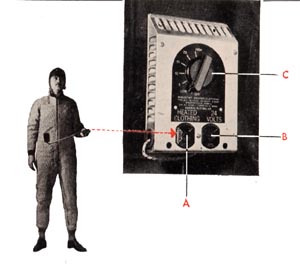 |
3 The Interphone The inside of a bomber is
noisy and the crew members are stationed far apart. To talk to your crewmates—to
tell them what you see and to get their warnings of enemy fighters— you use
the radio interphone system. You have a microphone—either a throat, oxygen
mask or handheld microphone — and earphones which plug into a jack box in
or near your turret. This jack box will be of two types, selector or non-selector.
The non-selector type jack box (A) is equipped with a push-to-talk button (B)
and a volume control (C). In the latest turrets an additional push-to-talk button
may be built into the control handles. The push-to-talk button for the selector
type jack box (D) is located on or near the control hand- | 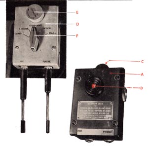 |
Restricted
T-6
dies. The jack box itself is provided with a volume control button (E) and the selector switch (F) with five different positions:
INTER—On this position you can hear and talk to all other crew members whose jack boxes are on INTER.
CALL—This position is used only when it is necessary to contact some crew member whose jack box switch is not on INTER.
COMP—When the switch is turned to this position you hear the radio compass receiver. LIAISON—At this position you will hear the pilot's Very High Frequency command equipment, used for plane-to-plane communication.
COMMAND—At this position you will hear the pilot's Medium Frequency command equipment, generally used for plane-to-ground communications such as landing instructions. To speak over the interphone system you will have to hold down a push-to-talk button. You will hear your own voice as you speak. Release the button immediately after talking so that you can hear your crew mates again. Speak naturally. Don't shout—it blurs your voice. Turn the volume control knob on the jack box to adjust the volume of your earphones. At high altitudes interphone operation is seriously interfered with if more than one push-to-talk button on the plane is held down at the same time. Don't attempt to speak while someone else is speaking except in emergencies. Try out the interphone before every mission. Make sure you can hear your crew mates clearly, and that they can hear you4 The Gun Camera
For taking photographs in combat or training, you will have a small bracket, usually near the gun sight, on which a gun camera can be mounted. A switch on the control panel operates the camera. When the switch is on, the camera will expose film as long as you are pressing the gun triggers.
5 The Trouble Light
For working in the dark, you will have a small trouble light with a switch and usually about six feet of cord. The socket is adjustable to provide either a floodlight or spotlight. Test the trouble light before missions. Make sure it goes on when you turn the switch. Examine the cord for worn places, and make sure the light bulb is seated firmly in its socket.
Restricted
T-7
The Turret Gunner's Job The preceding pages have described, in general terms, the compact yet complicated equipment which you will use as a turret gunner. You will have to know where all this equipment is in your own turret, how to prepare it for flight and make sure it is working properly, and how to use it in combat. You
will not be expected to be an expert turret mechanic; if something goes wrong,
trained maintenance men will repair it. But you will have to know enough about
how the turret works to recognize trouble when it occurs, and to spot it before—not
during—a mission. In the next few pages, you will become acquainted with the purpose, use, and care of such standard turret equipment as Plexiglas domes, safety switches, reset buttons, clutches, cutoff systems, and many others. With the information contained in these pages, you will then be ready to start specializing on the turret to which you will be assigned. | |
| Reset Buttons and Fuses | |
To protect the electrical circuits, most turrets have a set of either reset buttons (A) or fuses (B). The fuses operate just like those in a house; they blow out when a circuit gets overloaded or shorted and must then be replaced. The fuses are plugged in the turret's main switch panel; spares are usually carried in clips nearby or in a spare parts box. Reset buttons, which are usually found on the control panels, do the same job in a little different way. When anything goes wrong with a circuit, its reset button pops out and cuts off the current. To make the circuit work again, you must push the button back in. A combat tip on reset buttons: Sometimes, if you have been operating the turret at high speed, the electrical circuits which drive the turret will become so over-heated that the reset buttons will pop out as soon as you push them back in. If you are in the midst of an attack and must keep the turret working at all costs, hold the reset button in with one hand and operate the turret controls with the other. Do this only in real emergencies: You will overwork the circuits so badly that you will probably burn out motors or other equipment. |
|
Restricted
T-8
 | |
| The Safety Switches | |
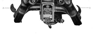
are built into the control handles. One type is set into the handle and is closed by squeezing it. The other and more standard type (A) is built out from the handle, like a wing, and is closed when you grasp the handle and press down the edge of your hand on the switch. Both have the same safety feature; the turret won't move unless one switch is closed. Test the switches by pressing one at a time. The turret should respond. Then release the switch. It should spring back into open position immediately, and the turret should stop cold. Try the switches several times. Always close them quickly to avoid burning them out. | |
| The Trigger Switches | |
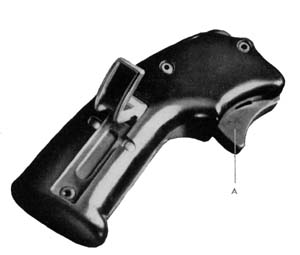 |
are always located right on the control handles (A), usually under
your index fingers. To test them, first make sure there is no ammunition in the
guns. Then press the triggers. A sharp click in the electric trigger control will
tell you if the firing circuit is working properly. Usually both guns are hooked
up to fire from either trigger—press one trigger at a time and make sure
both guns click. |
| The How and Why of Clutches | |
Clutches are provided on almost all turrets to allow you to disconnect the azimuth and elevation power gearing. Without this heavy gearing to move, it is easier to push the turret around by hand in making repairs and easier to run the turret manually in emergencies. The clutches are in different places in different turrets. Most of them are simply levers, which you push back and forth into the engaged or disengaged position. You can then make a final check by trying to push the turret around by hand and trying to move the guns up and down. If you have a hard time moving the turret, the clutches are properly engaged. Never take off or attempt to run the turret under power without first making sure that the clutches are engaged. It's like trying to drive your car with the clutch down to the floor. The mechanism is out of control. The turret will swing freely up, down, and around in the slipstream in a way that is dangerous to the navigation of the plane and may even cause a crackup. The sight cradle swinging around dizzily inside may crack your head. For the protection of others, always leave the clutches engaged when you leave the plane. | |
Restricted
T-9
| Leads Breezes Cannon Plugs . . . they carry your current . . . make sure the connections are tight. | 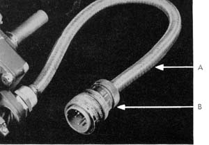 |
| In all turrets the current is distributed through electric leads usually covered with flexible metal conduits commonly called Breezes (A). These Breezes are important; if they are frayed or pulled out at the ends, the circuits won't work. Connections between Breezes are made by Cannon plugs (B)—plug-ins with a threaded ring and sleeve to hold them together. Before each mission, examine the Breezes closely. Watch out for frayed or worn Breezes and pay special attention to where they are attached to the Cannon plugs. Check the Cannon plugs to make sure they are plugged in and screwed up tightly. | |
| Testing the Limit Stops | |
| They prevent your guns from banging into the fuselage and must be tested before each mission. Run your guns into the fuselage, wherever they could possibly strike when moving up, down, or sideways. Take it easy, to avoid damage if the limit stops are not working properly. Unless the stops halt your turret before the guns hit the fuselage, report them. | |
| Checking Hydraulic Systems | |
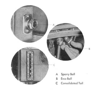 | In all turrets which operate hydraulically, the hydraulic systems must be filled with oil to the correct level to work properly. You will find a gage with a mark or screen to show the correct level. Check the gage every day. If the gage does not read FULL, report it. Make a habit of inspecting the hydraulic system and lines carefully for leaks. This is best done with someone operating the turret to keep pressure in the lines, while you go over the system with a flashlight. Examine the line tubing for cracks. Take particular note of swivel joints and tubing connections. If your turret has hydraulic gun chargers, make a careful check of their parts and lines, too. Report all leaks to turret maintenance. |
Restricted
T-10
| Use and Care of Booster Motors | |
The booster motors found in most turrets, to help lift the ammunition belts into the guns, always operate automatically. The motor, which turns a sprocket wheel on which the ammunition belt rides, is pulled toward the gun when the gun is fired; this automatically turns on the booster motor switch. When the gun stops firing, the pressure on the ammunition belt stops and springs pull the motor back to its normal position; and the switch cuts off. Test your booster motors before every mission,
before you have loaded ammunition over the sprockets. Tilt the motors toward the
guns. See if they start immediately and run smoothly. Then release the motors.
Make sure their springs pull them back to normal position and the motors stop
at once. But be careful around these motors: They are powerful, and their sprocket
wheels can cut off a man's finger. Occasionally vibration during combat causes
the automatic switches to lock; in that case the booster motors keep turning and
the ammunition belts are piled up against the guns, preventing the guns from firing.
If this ever happens in your turret, disconnect the electric cables which lead
to the motors. Your ammunition belts may not feed so smoothly, but at least you
will get your guns back to work. |
|
| Testing the Fire Cutoffs | |
Fire interrupter systems
are so complicated that adjustments are always handled by turret maintenance,
but you are responsible for testing the interrupter before missions to make sure
it is working. Test with the guns unloaded. Detach the Cannon plug from the electric
trigger control and insert a test light in its place. Squeeze the trigger and
swing the turret guns across the portions of the plane into which the guns could
fire. The test light should go out just before the guns come to bear on any portion
of the plane. This indicates the interrupter has gone into action. With a boresighting
tool check the distance from the point where the light goes out to the structure
of the plane into which the guns could fire. Repeat this procedure for each gun
and each danger area bringing the guns to bear first from one side and then the
other. Then do the same thing while moving the guns in elevation bringing them
first down on the danger areas and then up. Each gun should cut off with an ample
clearance on the danger areas. The amount of clearance should be about equal above
and below the danger areas and to either side. If the guns fail to cut off, if
the clearance is too small or if the clearance is not the same in all directions,
report it at once. It is not wise to put complete confidence in the fire interrupter
particularly after you have been firing long bursts because it is possible that
a round may "cook" off in the gun even though you do not press the triggers. |
|
Restricted
T-11
| The Dome | |
 | .
. . it serves as your windshield |
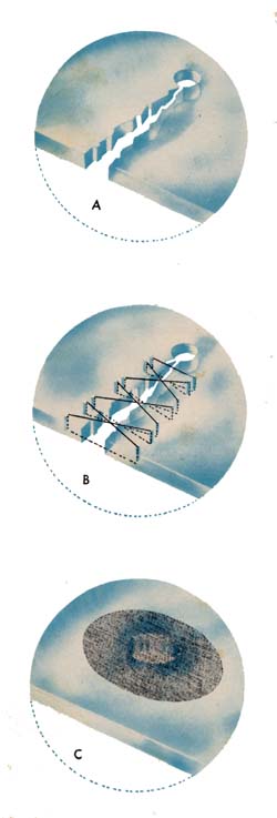
All turrets have Plexiglas domes or panels to protect you from the slipstream and still give you a clear view of the sky around you. Plexiglas is a glass-like plastic. It scratches easily; and the first rule is to be careful with it. Clean Plexiglas with plenty of soap and water. Never use a dry cloth—it may scratch, and it will build up static electricity that attracts dust. Never use hot water because heat softens the plastic. You may use a little plain kerosene or naphtha to remove grease or oil, but beware of all cleaning sprays or solutions. They usually contain chemicals which soften and crack the Plexiglas Only qualified maintenance men should repair major scratches, cracks, or holes in Plexiglas But sometimes you may have to make temporary repairs. Rub out minor scratches with automobile or furniture wax, always using a circular motion in rubbing. This gives a good gloss and helps prevent future scratching. In fact, an excellent scratch preventative is a good simonizing job on the whole dome. At the first sign of a crack in Plexiglas, notify maintenance. If cracks aren't caught soon enough, they rapidly grow into major breaks under further strain and the ripping force of the slipstream. If you have to make a temporary repair yourself, first drill a hole about 1/8 to 3/16 inch in diameter in the end of the crack (A); this will distribute the strain over a wider area. Then drill a series of small holes on each side of the crack, about a half inch away, and lace the two edges together with wire (B). This will prevent the crack from spreading. If you have to make a temporary repair on bullet holes in Plexiglas, use a half-round file to trim the hole and any cracks surrounding it to a circle. Then put on a round patch of wing fabric or thin Plexiglas or cellulose acetate sheeting (C), using "dope" or other solvent on both surfaces to make them stick. Mask the area around the hole so that the "dope" or solvent, which softens and cracks the Plexiglas, can't spread. If you have no patching materials handy, whittle out a wooden plug for the hole until you can have permanent repairs made. |
Restricted
T-12
| How to recognize "Creep" | . . . it is a common turret ailment which requires immediate repairs |
| When your turret is suffering from "creep"—a fairly common turret ailment—it is in no shape to go into combat. Watch for creep when you test operation of the turret before each mission. It is easy to recognize. When the control handles are held neutral the turret, instead of stopping, continues to creep a little farther in one direction or another. If you try to use the turret in combat, every time you try to train your guns on the target the turret will go a little beyond, so that you will always miss your mark. Report even the slightest amount of creep immediately. At the same time, watch for "blinding". Make sure the turret does not stick or drag. | |
| The MK 9 Reflector Sight | |
Most Navy turrets are equipped with a MK 9 Reflector Sight mounted directly in front of you at eye level. This sight is a sturdy mechanism, but it will not stand being used for a hand grip when you climb into the turret. Normally in harmonization you will adjust the turret guns to the sight, but sometimes there may not be enough adjustment in the gun mounts to do this. If this is the case, it will be necessary to make adjustments on the sight head, to line up the sight with the guns. Elevation adjustment is obtained by loosening the nut (Y) on the side of the sight and turning the boresighting cam (Z). Azimuth adjustment is obtained by loosening the adjustment nut (X) on the side of the sight and rotating the hood in azimuth until the desired adjustment is reached. Before a mission, test the sight bulb, making sure both filaments are good. If either is burned out, replace the bulb. Check the rheostat for operation by turning it from dim to bright. Clean the reflector plate of the sight. | 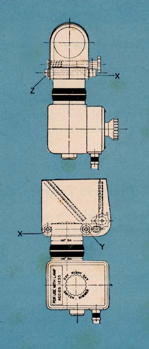 |
Restricted
T-13
| The Turret Guns |
A machine gun is always a machine gun, whether in a turret or on the ground. It requires the same care, the same adjustments, the same field stripping and detail stripping to enable you to clean it, oil it, and inspect it before and after every mission. The pre- and post-flight checks described in the Guns section must be followed to the letter. The special equipment which makes the caliber .50 easy to use in the crowded space of the turret will be installed for you by turret maintenance, and you will never have to remove it. You will leave the gun casing group mounted in the turrets, and will not install, remove, or adjust the special charging unit or the ejection chutes provided in some turrets to carry away used links and brass. You will simply take off the backplate and then pull out the "guts" of the gun—the bolt, oil buffer, and barrel groups—to clean, inspect, and oil them. But you will have to know from which side the guns feed, so that you can reassemble the bolts properly. And you will have to know how to install and adjust your electric triggers and how to check the charging units to make sure they are working properly. |
1
Assembling the Guns |
2
Electric Trigger Controls |
Restricted
T-14
3 Adjusting the Electric Trigger Controls | |
| Be sure the headspace adjustment is correct as shown in the section on machine guns. Make sure the firing circuit is on. Then follow this procedure for adjusting each electric trigger: | |
 | |
| A
Turn the adjusting cap to the right, clockwise, until it stops. B Turn the cap to the left, counterclockwise, one notch at a time, charging and attempting to fire the gun each time, until you reach a notch where the firing pin releases each time the gun is charged. Test it at this point two or three times. Then turn the cap another three notches counterclockwise. C Check the adjustment at this point with a standard fire and no-fire timing gage. Place the .020-inch gage (FIRE) between the trunnion block and barrel extension, charge and fire the gun, and make sure the firing pin releases. Then use the .116-inch gage (NO FIRE) and make sure the firing pin does not release. | |
4 The Charging Unit | |
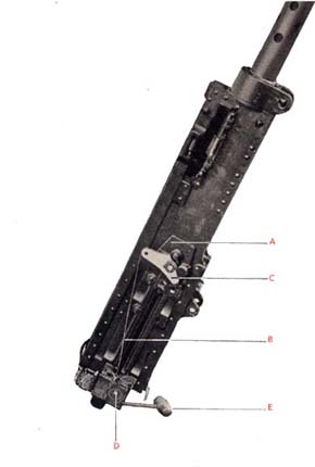 | Most charging units operate mechanically, by a pulley-and-cable arrangement. Some work hydraulically. But the purpose of all charging units is the same—to enable you to charge your guns easily in the crowded space of the turret. On mechanical units, you will simply pull two cables, one for each gun. On hydraulic units, you will press a button which charges the guns automatically. Before every mission test your charging units— without ammunition in the gun—until you are satisfied they are working properly. If you have a mechanical unit, make sure the charger plate (A) is properly bolted and safety wired to the gun's receiver. Make sure the cables (B) are attached properly to their levers (C), are free from kinks, and ride smoothly in their pulleys (D) when you pull on the charger han- |
Restricted
T-15
| dies (E). If your turret uses a hydraulic charger, watch for leaks as you test the charging action. In loading ammunition into your guns before the takeoff, you will simply push the first round of the ammunition belt into the feedway. The gun will then have to be charged twice, after you are in the air, to make sure that the first round enters the chamber and is ready to fire. Your flight commander will signal when to charge the guns. | |
5
Loading Ammunition | 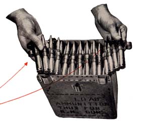 |
| This is the standard method of folding into the ammunition can regardless of the shape or size. Note the pattern in which the rounds lie in the can. All cans are loaded starting with the single-link end of the belt first, so that the final topfold ends with the double-link end of the belt. The double-link end must always feed toward the gun. This can is loaded for a gun with right-hand feed. For left-hand feed, the double-link end must feed from the other side of the can. | To
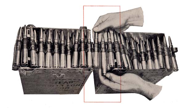
connect one ammunition belt to another, use this method. Use a single cartridge
as a connecting pin to join the double-link end of one belt to the single-link
end of another. Make sure the connecting round is pressed into the link all the
way, in line with both belts. |
 | |
Restricted
T-16
| Pre-Flight and Post-Flight Checks |
| . . . in all turrets, they are your life insurance |
No matter what turret you use, your most important job as a turret operator will be making pre-flight and post-flight checks. You will check lists at the end of each individual turret section in the following pages, showing step by step every procedure you must follow from inspection before the flight, through the mission to the post-flight check after you return. The preflight is particularly important, for it is the final, crucial examination of your turret—including all the specific checks already discussed—to make sure it is ready for battle. Unless you make these checks with great care, never omitting a single step, you cannot expect your turret to stay in working order. And if your turret ever fails in a pinch, you are out of luck. A caution on preflight checks: You will have to run the turret on the bomber's auxiliary power, which means that you will be drawing on the same batteries that the plane depends on for takeoffs. Always have your crew chief supply the power; never use it without the crew chief's knowledge. Never operate the turret on the batteries alone. At the end of each preflight, which naturally is different for each turret, you must make a general visual check. This is the same for all turrets. Run your eyes slowly over everything inside the turret. Then get out and do the same from the outside. Watch for such things as cracks or damage in the turret castings, loose covers on junction boxes, loose or missing nuts and bolts, nuts not safely wired properly, and so forth. Don't be afraid to report anything that seems to be wrong, however small it may appear. These checks are often the difference between life and death. They are double indemnity insurance on the lives of your entire crew. Don't skip anything. Make them the most careful and serious jobs of your Navy career. |
| How to Use the Rest of This Manual |
| . . . it will describe each turret individually |
Up to now, this manual has discussed only the features common to all turrets; the instructions up to this point apply to all turrets in use by the Navy today. In the following pages, you will find individual descriptions of each turret, with special instructions for its use, care, and inspection. Described in the manual are eleven turrets, in this order: |
Restricted
T-17
| GRUMMAN BALL | GRUMMAN 150SE-1 & 2 |
| ERCO TEAR DROP | ERCO 250TH-1 & 2 |
| ERCO BALL | ERCO 250SH-2, 2A & 3 |
| MARTIN BALL | MARTIN 250SH-1A & 2 |
| MARTIN ELECTRIC UPPER DECK | MARTIN 250CE-7 THROUGH 21 |
| MARTIN HYDRAULIC UPPER DECK | MARTIN 250CH-1 & 3 |
| MARTIN HYDRAULIC TAIL | MARTIN 250CH-2 |
| CONSOLIDATED TAIL | CONSAIR 250CH-3, MPC 250CH-6 |
| SPERRY RETRACTABLE BALL | SPRERY 350SH-1 |
| BENDIX UPPER DECK | BENDIX 250CE-3& 4 |
| EMERSON BOW | EMERSON 250CE-1 |
| The official Navy name for turrets gives you a complete story on who designed the turret, the number of guns, the shape, the type of power and the model airplane for which it was designed. In other words, Martin 250CH-1 means Martin was the designer, 250 is two cal. 50 machine guns, C stands for cylindrical in shape, H for powered hydraulically and -1 indicates the model airplane the turret was built for. Other shapes are T for teardrop, S for spherical and R for remote control. | |
As a combat crew member, you will probably specialize in only one turret. But you will have to have a working knowledge of the other turrets in your plane, so that you can take over whenever necessary. You will find that knowledge in the following pages, and in your classroom instructions. As far as possible, this manual has been stripped down to the practical, working information that the gunner needs under everyday conditions. For each turret, the order of presentation will be as follows: 1
HOW TO GET IN 2 HOW TO OPERATE THE TURRET (Where to find the switches, and how to turn them on.) 3 WHERE TO FIND THE AUXILIARY UNITS | 4
HOW TO GET OUT 5 HOW TO ADJUST THE SIGHT 6 HOW TO ADJUST THE GUNS 8 HOW TO HARMONIZE GUNS AND SIGHT 8 HOW TO LOAD AND MOUNT THE AMMUNITION CANS 9 A CHECK LIST of the preflight and post-flight routine on each mission. |
Restricted
T-18
 |
GRUMMAN
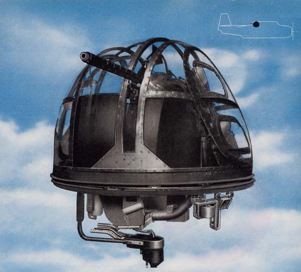
BALL TURRET The Grumman 150SE Turret, the only turret in the TBF Avenger, takes care of beam, overhead, or tail cone attacks on the airplane. In this turret, which is of the ball type, the gunner moves with the gun and sights in elevation and azimuth in the direction he turns the control handle. It is powered electrically and packs a mighty punch in its single cal. .50 machine gun. The turret has been
produced in two models—the Grumman 150SE-1 used in the Avenger 1 and the
Grumman 150SE-2 used in the later model Avenger 2. |
Restricted
T-19
Facts and Figures POWER |  |
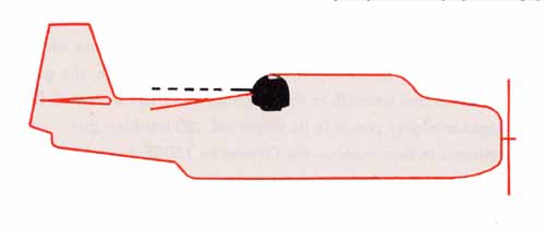
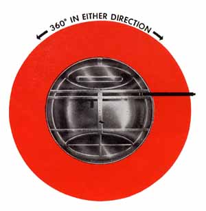 | ELEVATION In elevation the ball and gun can be raised 85° above horizontal and be depressed 30° below horizontal. SPEEDS The turret has two speeds—normal tracking and high speed. ARMOR The armor plate protection in the turret consists of 1/2" thick armor plate in the front and sides,-1/4" thick armor plate under the seat, and 1 1/2" thick bullet-proof glass to protect the gunner's face. |
| AZIMUTH The turret can move—a full circle—in azimuth. | STOWING
POSITION The stowing position is 0° elevation and 180° azimuth, gun pointing straight aft. |
 | |
Restricted
T-20
| Getting
In Having been introduced to the turret in the Grumman Avenger, you will now want to know how to get into it. Pursue the following steps carefully, or damage to the turret might result. | |
| Before entering
the turret, make sure the main battery switch on the pilot's control switch
panel is "on". Then check to determine if the emergency switch
in the junction box is "on". This junction box is attached to the left
bulkhead in the bombardier's compartment. To turn this switch off or on, it is
necessary to remove the cover of the junction box. | 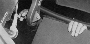 |
| A flap of !4" armor plate is hinged to the front of the turret's seat and stowed in the up position with a spring loaded pin. Pull out the stowing pin and swing the armor plate flap down. Facing forward enter the bottom of the turret. Reach up and grasp the side armor plate with your left hand. As you pull yourself up into the seat twist around so that you are facing aft. Do not use the sight or the control handle as a hand grip. Then place your feet on the front armor plate above the flange. Pull up armor plate flap, and lock it in up position with the stowing pin. It is very important that this armor plate flap be stowed in the "up" position before you put the turret into operation. If left down, you can seriously damage the turret as well as the airplane. | |
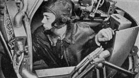 | 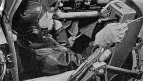 |
| Look through the sight and determine if it is at the proper height.
If the sight is not, loosen the adjusting bolts that hold the sight bracket and
raise or lower it to adjust the height to your liking. Don't forget to secure
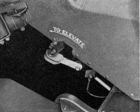
the sight bracket adjustment bolts. Next to your left knee is the elevation
manual crank. Check to see | 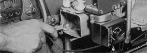 |
Restricted
T-21
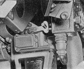
that the crank is disengaged and that the handle is stowed in its retaining clip. Outside the ball on the right side under the right trunnion at track level is the azimuth clutch. Make sure that this is in the engaged up position. Fasten and adjust your safety belt—you will need it in this turret. | |
 |  |
| Operating the Turret | .
. . Where to Find the Controls . . . How to use them |
| Seated in the turret, you are now ready to begin to operate it. Directly in front of you and below the bullet-proof glass is the control box in which is installed the pistol grip control handle, and the master switch. This control box should be in the stowed position. On the right side is the stowing lever. Push down on it and the control box will drop into operating position. Make sure the lever is reengaged. Next to your left shoulder is the control panel. Reach over and flick on the train (azimuth) and elevation switches. Then turn on the master switch on the control box in front of you. The turret is now ready for instant action. Remember at all times
to keep your feet up on the front armor plate and your hands away from the moving
parts while operating the turret. |
Restricted
T-22
Grasp the pistol control handle, at the same time squeezing the safety switch in the handle to put the turret into operation. To move the turret operate the pistol grip control handle as you would a pistol. To roll the turret up, point the pistol grip up; to roll it down, point the grip down. The same is true for movement right or left. The pistol control grip also contains a high speed button for increasing the speed of the turret for slewing from one extreme position to the other. Merely press the button on the back top of the grip with your thumb to bring this high speed control into operation. Releasing the control grip will automatically return the gun to the trailing aft position and cut off power to the drive motors. | 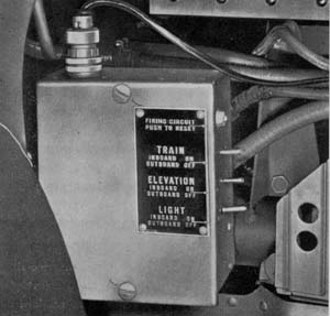 |
Right under your index finger in the pistol grip control handle is the trigger switch for firing the gun. Charging the guns
in the turret is a manual operation. In front of your left knee is the charging
handle. Grasp the charging handle with both hands, one above the other,
and give a hard pull all the way back. Then quickly release the handle and let
it slide forward by itself. To hold the bolt back in the gun to facilitate boresighting
and the removal of jams, a latch is provided to lock the gun charging handle in
the back position. | 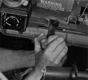 |
Using the Auxiliary Units The oxygen system of the turret is dependent on the main oxygen system of the airplane. The oxygen is brought into the turret through the slip ring assembly at the bottom. Here is attached a flexible hose, which conducts the oxygen to the gunner's mask. The interphone jack box located next to your right knee is where you plug in your inter-phone jacks for your headphones and throat microphone. This box is also provided with a volume control and a wave band selector switch. | |
Restricted
T-23
| In this turret no heating suit outlet is provided. However, in the bombardier's compartment directly beneath you, you can attach your heating suit to an outlet provided there. A stationary trouble light located above the gun is installed in a bracket which is attached to the inboard side of the Bell Mount Adapter. The light switch is located on the control panel. As soon as the (battery switch in the pilot's cockpit is turned on, you are able to turn on the trouble light in the turret and also the Mk 9 sight by means of its built-in switch. Provisions are made for mounting a gun camera on the top left side of the bullet-proof glass face plate frame. To operate the camera depress the safety switch and trigger switch. | 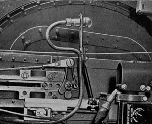 |
Getting Out To get out of the turret be as careful as you were in getting in. Remove your hand from the pistol control handle, and the turret will return to the stowing position, 0° elevation and 180° azimuth—gun pointing straight aft. Push down the latch on the right hand side of the control box and raise the box up to its stowing position, allowing the latch to reengage, and secure the box in place. When stowing the control box, do not lift it by its pistol grip control but rather by the control box itself. Otherwise you can damage the internal mechanism of the box. Turn off all switches and disconnect the auxiliary units you have been using. Unfasten the safety belt. Reach down and pull out the stowing pin which holds up the armor plate flap beneath you and push down the flap. Climb out of the turret facing aft, feet first, using the side armor plate as a hand grip to assist you in getting out. | |
Restricted
T-24
Once outside the turret, push the armor plate flap up to its stowing position and lock it in place with its stowing pin. Emergency
Exit | 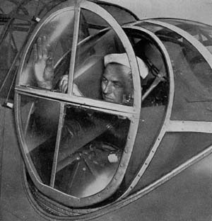 |
Getting Out | |
The
Sights | 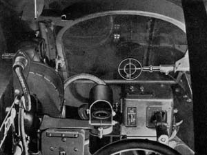 |
Restricted
T-25
Adjusting
the Gun | 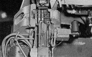 |
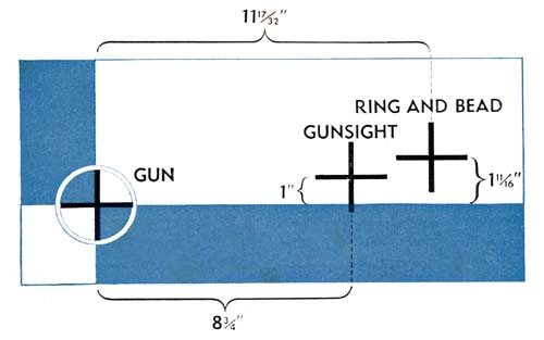
Harmonizing the Sights
to the Gun Now turn on the reflector sight switch, which is built into the sight, and make whatever adjustments are necessary on the sight head to line up the dot squarely on the reflector sight cross on the pattern stand. To complete the job line up the auxiliary ring and post sight on its respective cross on the pattern stand. If your plane is land based, another method is to boresight the gun on some small object, such as a tree or chimney, at least 1000 yards away. Then adjust the sight head until the dot of the sight is squarely on the object. Both methods described here are parallel boresighting. | |
 | |
Restricted
T-26
Loading Ammunition | 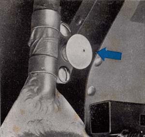 |
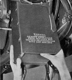 | Installation
of the ammunition can in the turret is done from the outside. Hold the can with
the right hand on the bottom and the left hand near the top so that the guide
rails on the can register with the guide track. Push upward until the can is approximately
half way in the stowed position, and the can will latch itself. Now use both hands
at the bottom of the can to push it home where it automatically locks in place.
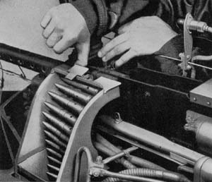
Hook the cable lock on the bottom of the ammunition container. 1. To load the gun, open the cover on the top of the gun. 2. Open the feed chute cover on the left hand side of the gun; slide your hand through the feed chute down into the ammunition can; pull up the ammunition belt and insert the first round through mouth of feed chute into the machine gun receiver. (The non-return ratchet prevents the belt from falling back into the feed chute.) |
Restricted
T-27
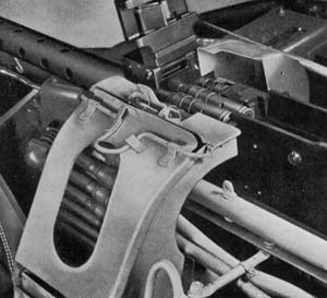
3. Pick up the extractor, pull
back the charging handle approximately !4", and pull up the belt until the
first round is aligned against the cartridge stop. Drop the extractor between
the first and second rounds. Slam the cover plate back into position | |
 |  |
| Removal of Empty Cartridge Cases and Links | |
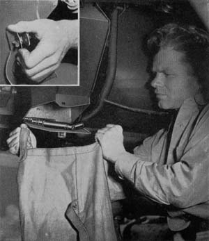 | The
empty links and cartridge cases are collected in a container almost directly under
the gun. A lever secured with a winged Dzus fastener is mounted above the elevation
hand crank to dump the container. Free the lever and push it down. Catch the empty
links and cartridge cases in the special bag provided, or in some other container.
Allow the ejection door on the bottom of the container to slam shut and rescue
the lever with its winged Dzus fastener. Always remember to empty the expended ammunition container when you load a new can of ammunition into the turret. This is very important because if the container becomes overfilled, the gun will jam. |
Restricted
T-28
Preflight Routine . . FOLLOW STEP BY STEP | 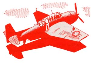 |
| 1.
Completely reassemble the gun in the turret, making sure the gun is assembled
properly to feed from the left. 2. Lock the bolt back by latching the gun charging handle in the aft position. Check harmonization of the gun and sights by boresighting on a pattern stand or some other object 1000 yards or more away. 3. Try to rock the gun in its mount. Make sure it is securely mounted. Check to see if the nuts are properly safetied. 4. Check to determine if the azimuth clutch is in the "up" position so that the turret cannot be pushed around by hand. 5. Check the elevation clutch and hand crank. Determine if it is not engaged and if the handle is stowed in the clip provided for it. 6. Hand charge the gun several times to test if it is working properly. 7. Inspect the flexible electric conduits (Breezes) to determine if they are frayed or broken. 8. Check all Cannon plugs to see that they are properly seated and screwed up tight. 9. Check the oxygen connections to make sure that they are tight. 10. Make sure the Plexiglas dome, escape hatch, and bullet-proof glass face plate are clean and properly secured. 11. Check for ease of operation in elevation and azimuth. Depress high speed button and check the turret in slewing. | 12.
Remove your hands from the pistol control handle to determine if the turret returns
to the stowing position. While in the stowing position check for turret "creep." 13. Operate the turret to extreme elevation to determine if the limit stops are functioning properly. 14. With guns completely depressed, carefully rotate the turret to determine if the contour follower keeps the gun from swinging into the fuselage. 15. With power on, safety switch depressed, squeeze the trigger and listen for the "click" of the electric trigger control. 16. Insert a test light in place of electric trigger control and with trigger depressed swing the turret across the portions of the ship into which the gun could fire. The test light will go out in this area. With a boresighting tool check the distance from the surface that the interrupter cuts out. 17. Turn on the sight switch and rotate the sight rheostat from dim to bright to adjust the brightness of the reticle to existing light conditions. Make sure the rheostat is working properly. Try both filaments of the sight bulb. If either is burned out, replace the bulb. Make sure the reflector plate of the sight is clean. 18. Open the spare light bulb stowing box on the sight bracket to determine if you have the required number of spares. |
Restricted
T-29
19.
Plug your headphones and throat microphone into the inter-phone jack box to test
if your crew mates can hear you and you can hear them. | 23.
Make a complete visual check of the turret inside and out. 24. Load the ammunition can and install it in the turret. Feed the belt up through the feed chute into the feedway of the gun. You will not charge the gun until you are in the air and so ordered by the pilot. |
Before Landing 1.
Let go of the pistol grip control handle, and the turret will return to its stowing
position—0° elevation and 180° azimuth, gun pointing straight aft. |
4. Check all switches and make sure they are off. 5.You will remain in the turret during landings. |
1.
Disconnect any auxiliary units that you have been using. | After Landing
|
Restricted
T-30