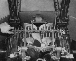
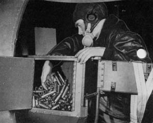
Erco tear drop turret

Erco Tear Drop Turret
ERCO 250TH-1 AND 2

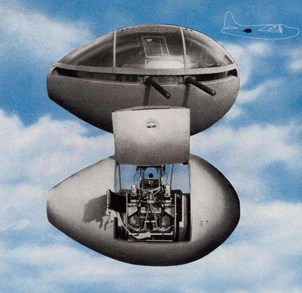
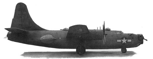
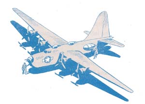
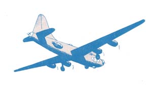
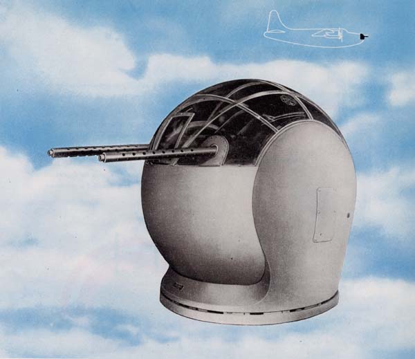
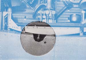
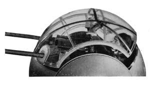
The Erco 250TH Turrets have the approximate shape of a tear drop. They are installed in the waist positions on either side of the PB4Y-2 airplane—the Erco 250TH-1 on the starboard side and the Erco 250TH-2 on the port side. With their wide cone of fire they protect the plane from beam or belly attacks, besides offering a considerable area of protection from above. In operation they are somewhat similar to a ball type turret inasmuch as the gunner moves with his guns and sight in the direction he moves his control handles.

Restricted

T-31


Facts and Figures

POWER
The Erco Tear Drop operates hydraulically on pressure built up by a hydraulic pump driven by a constant speed electric motor.

SIGHTS
Its sight is a standard Navy Mk 9 reflector sight, fully described in the introduction of this section.

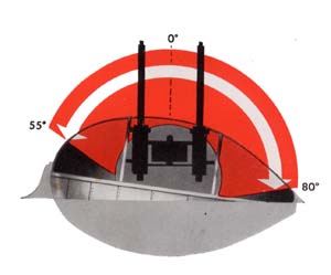
Elevation limits
Azimuth limitsELEVATION
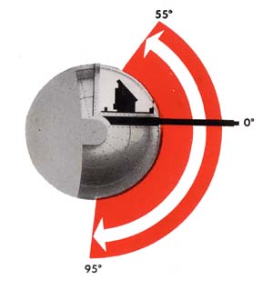
Both turrets can raise their guns 55° above horizontal in elevation and depress them 95° below horizontal.

ARMOR
The armor plate in the turret protects the gunner from fire an any direction he turns the guns. It consists of three groups: (1) 11/2" thick bullet- proof glass in front of his face, (2) 5/16" armor plate in front of his body, and (3) 5/16" armor plate under his feet.
AZIMUTH
In azimuth the Erco Tear Drop turret allows the guns a movement of 135°, 55° towards the bow from the beam and 80° towards the tail of the airplane from the beam.
STOWING POSITION
The stowing position is 0° elevation with guns pointed in the extreme aft position in azimuth (80° aft of the beam).
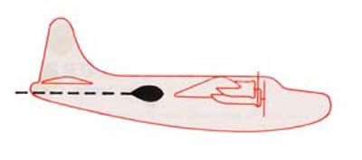
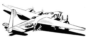
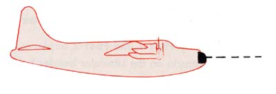
PB4Y-2 silouette

Restricted

T-32


Getting In
Now that you have been introduced to the Erco Tear Drop Turret, the next thing you must learn is how to get in the turret. You will find this an easy job. However, you must pursue the following steps carefully, or you might seriously injure yourself or damage the turret.

To begin with, have your flight engineer throw on the waist turret switch on the flight engineer's panel.

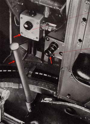
On a junction box, mounted to a bulkhead conveniently located near the turret, is the main power switch, along with a push release button switch and a red indicator light. Flick this main power switch to the on position. The push release button is provided for emergency use only in turning off the power to the turret.

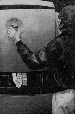
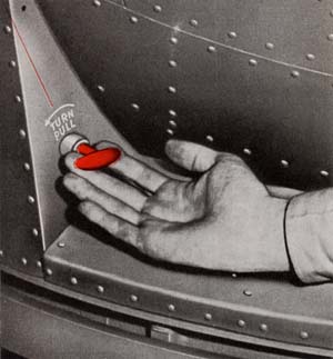
You are now ready to get into the turret. Turn the handle counterclockwise on the entrance door in the back of the turret and raise up the door to its stowed position. Inside the turret on the forward inboard side, right next to the

Opening turret entrance door handle
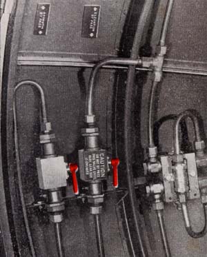
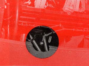
By-pass valvesentrance door, you will see two levers painted red and marked elevation by-pass valve and azimuth by-pass valve. Make sure these levers are in the down position. As your turret is in the stowed position, it will be necessary to move the seat and guns in azimuth to a right angle from the center line of the plane for you to get in. To do this, raise up the azimuth by-pass valve lever which frees the seat and guns so that you are able to move them around to the desired position. Lock the seat and guns in position by turning the azimuth by-pass valve lever down.

Restricted

T-33


Entering the turret


Unhook the back of the turret seat and swing it back. Be sure you keep the shoulder harness over the back of the seat.

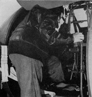
Duck your head under the top of the door and put one leg into the turret. Grasp the tubing on either side of the sight to assist yourself and slide in on the seat. Reach around behind you and snap the seat back rest into place.


Now that you are seated, take a look through the sight to determine if you are at the proper height. If not, reach down between your legs under the seat and grasp the seat adjustment lever so that you may raise or lower the seat to the desired position.

Seat adjustment lever

You have yet to close the entrance door; so reach around in back of you to the side and lift up again the azimuth by-pass valve lever, which we spoke about before you entered the turret. This frees your turret in azimuth so that you are able to move your seat around freely. Using the upper ribs of the turret as a hand grip, push your seat around so that you have your guns pointing aft. Reach around and lift the bottom of the door, freeing it from the locks in the channel guide. Then carefully let the entrance door down. Grasp the handle in the top section of the door; open the door latching handle in the bottom section, and pull the door in sharply, releasing the latching handle so that the door locks. Check the latching handle to see that it is completely secured. Now turn the azimuth by-pass handle to the down position, making the turret ready for power operation.

Put on the shoulder straps and fasten the safety belt. You will need them in this turret.

Restricted

T-34


OPERATING THE TURRET


. . Where to Find the Controls
. . How to Use Them

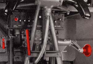
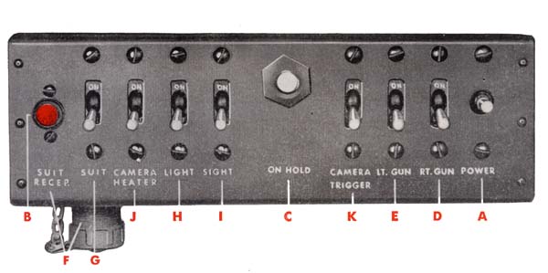
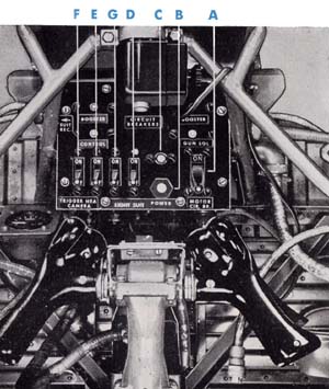
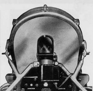
The control panel with all the switches for operating the turret is directly in front of you, behind the control handles. With a few clicks of the switches you will be able to put the Tear Drop Turret into operation.

Control handles
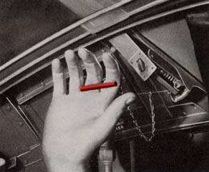
Clutch leverFirst of all, check to determine if the manual azimuth and elevation clutches are disengaged before attempting power operation. This is very important as each clutch is equipped with a switch which cuts off the power to the turret when the clutch is engaged. The azimuth clutch is operated by a red bar handle next to your knee. Check to see that it is in a stowed

position and that the turret will not move when you turn the azimuth hand crank, located next to the other knee. The elevation clutch has a red handle lever on the forward trunnion of the turret, which should be in the up position. To insure disengagement of the elevation clutch, operate the elevation hand crank in the top aft portion of the turret. The turret should not move.

With these checks made you are now ready to turn on the power. Hold down momentarily the

Hand cranks

Restricted

T-35


power switch (A) on the control panel; the red indicator light (B) should light up, as well as the one on the junction box outside of the turret. These lit-up indicator lights show you that the power is on in the turret. To operate the turret, grasp the control handles in front of you, depressing the safety switches which start the pump motor. Turn the handles in the direction you desire to move the turret. For azimuth (right or left), the handles are operated like those of a bicycle. For elevation, move the upper part of the handle grips backwards, and for depression, move the top portion of the handles forward. Don't jerk the controls—move them smoothly and deliberately. If for any reason the power in the turret cuts cut, it may be possible that the circuit breaker to the pump motor is overheated. As a measure of immediate action, depress with one hand the on-hold button (C) which will by-pass the circuit breaker. Operate the control handles with the other hand.

The guns may be fired singly or together. They are controlled by gun selector switches marked right gun (D) and left gun (E) on the control panel. The triggers are right under your index fingers on both control handles. Either trigger will fire both guns, together or singly, as you may determine by your gun selector switches. Under your thumb on the top front part of the control handles are the red interphone buttons. Press either or both buttons when you wish to speak.

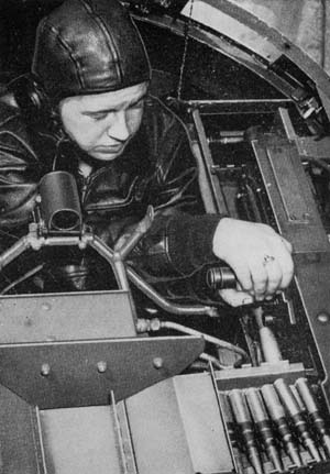
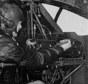
In front of you, on each side, are the two caliber fifty machine guns with hand charging handles on the outboard side of each gun. Reach forward, palm up, and grasp the hand charging handle firmly. Give a quick pull backward; then release the charging handle smartly and let it slide forward by itself. Repeat the procedure for the other gun.

Restricted

T-36


Using
Auxiliary Units

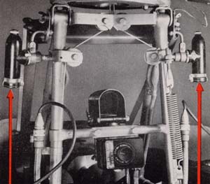
The turret is provided with a diluter demand type oxygen system fed into the turret through the aft trunnion from the airplane's main oxygen system. To control the amount of flow of oxygen to the oxygen mask, a regulator is mounted in the bracket in the top inboard side of the forward section of turret. The cord to your heating suit is plugged into the suit receptacle (F) in the bottom of control panel and is turned "on" and "off" by a heating suit switch (G) in the same panel.

Trouble lights
Trouble lights, of the spotlight type, provided with swivel joints to direct their beams, are mounted at the top of the sight supporting structure. The light switch (H) to control these lights is on the control panel. To turn on the sight, flick the sight switch (I) to the on position on the control panel. No other switch in the turret need be on.
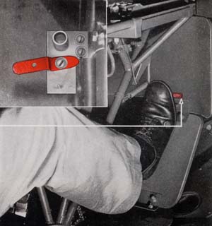
Provisions have been made for installing a camera in back of the armor plate in front of the bullet-proof glass face plate. To operate the camera turn on the camera heater (J) and camera trigger (K) switches on the control panel. Squeezing the triggers will put the camera into operation. The interphone jack box is located above your hip on the aft side of the seat. This is where you will plug in your interphone jacks for your head set and microphone. If the power fails, a foot firing mechanism is provided. Reach down by your knee and turn up the red safety catch. Then by depressing the red bar above your foot the guns are fired.
Foot firing mechanism

Restricted

T-37


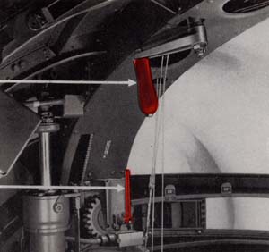
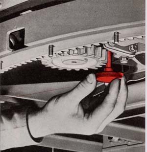
Manual elevation and azimuth hand cranks are provided to move the turret without power. To put them into use it is necessary to pursue the following procedure: Release the red azimuth clutch bar next to your knee; then reach in back of you and lift the azimuth by-pass lever. By operating the hand crank next to your other knee azimuth movement is obtained. For elevation manual operation, engage the elevation clutch on the front trunnion by turning down the red handle; then raise up the elevation by-pass lever in back of you. By turning the elevation hand crank at the top of the turret you will be able to move the turret up or down. If either of the clutches do not slip in easily, work the hand cranks back and forth until they do.

This manual method of operating the turret will be of little use to you as a gunner in combat. However, you will find this manual control very helpful in positioning the turret and in harmonizing the guns and sight when a small amount of carefully controlled movement is desired.

Operating hand crank

Getting Out
Get out of the turret just as carefully as you got in. Turn the turret to the stowing position —0° elevation and 80° aft of the beam in azimuth—guns pointing aft. Disconnect any auxiliary units you may have been using. Reach around in back of you and unlock the door latching handle. Grasp the handle on the upper section of the door and push out. With your other hand, grasp the bottom of the door, lift up, and stow the door in the channel catches provided. Move the turret to 0° elevation and to the beam in azimuth. Turn off all switches. Unclamp the seat back and climb out of the turret. Reinstall the seat back. Reach inside the turret and lift the azimuth bypass lever and shove the guns and seat around in azimuth by hand to the stowing position— 0° elevation—guns pointing aft. Depress the azimuth by-pass valve lever.


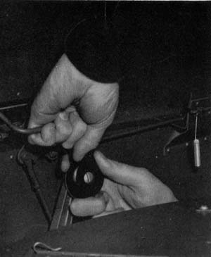
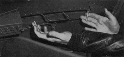
Pulling out hinge pins

Emergency Exit
It may be necessary to get out of the turret in a hurry. If that is the case, an emergency exit is provided through the entrance door, either

Restricted

T-38


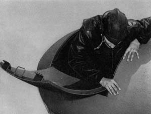
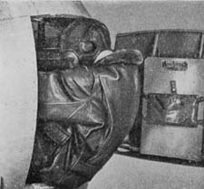
outside of the airplane or into the airplane. To escape outside of the airplane turn the turret down to its maximum depression to bring the upper section of the entrance door to the outside of the airplane. Pull out the two pins that hinge the two sections of the entrance door together and push up the upper section so that you can crawl out of the turret. To escape into the airplane run your turret to 0° elevation and to a right angle from the center line of the plane in azimuth. Pull out the hinge pins to the entrance door and push the door out. If your plane is still in the air, don't forget to snap on the chest pack parachute which is stowed on the aft inboard side of the turret.
Exiting the turret

Preparing the Turret for Combat
The preceding pages have illustrated how you get in and operate the Erco Tear Drop Turret, and how to get out again. From this information, you could take over and operate the turret in combat. If you specialize in the Erco Tear Drop, however, that will only be part of your duties. The rest of your job—adjusting the sight and guns, harmonizing them, and loading the ammunition for a mission—is explained in the following pages.

PB-4Y-2 aircraft
The Sight
The Navy Mk 9 sight fits into the gunsight bracket directly behind the laminated bulletproof glass. To adjust the sight, as may be sometimes necessary in harmonizing it with the guns, make your adjustments on the sight head. For full instructions in making these adjustments see the section on the Mk 9 sight in the general introduction of this section.

Restricted

T-39


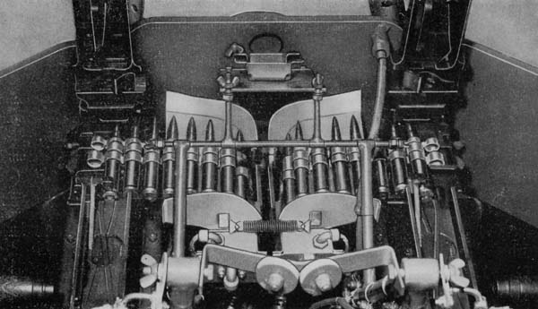
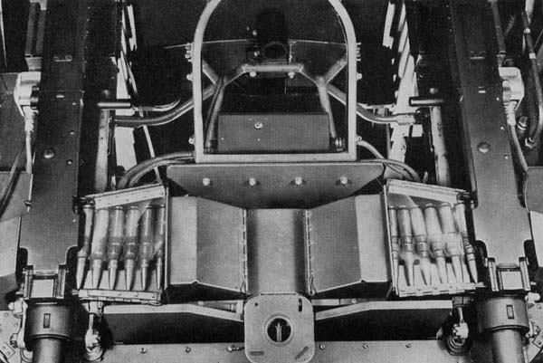
Center ammunition feeds
Adjusting the Guns
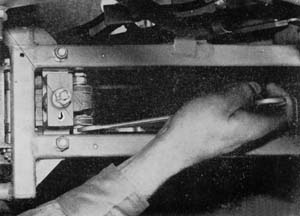
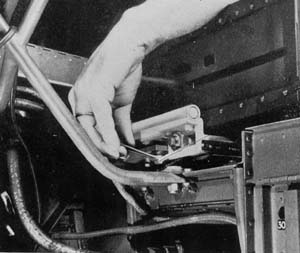
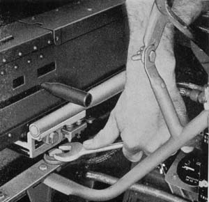
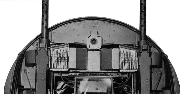
The guns are mounted in the Erco Tear Drop Turret to feed from the inside—the right gun feeds from the left and the left gun feeds from the right. Each gun is mounted in a Bell Mount Adapter. The rear support of the adapter is provided with an assembly containing an elevation adjustment bolt and an azimuth adjustment bolt to move the gun up, down, or sideways. When boresighting, adjustment of the guns is accomplished by holding the proper adjustment bolt head with a wrench and after loosening the jam nut and nut, turning the bolt. On completing your boresighting don't forget to tighten both nuts on each adjustment bolt.
Adjusting the elevation boltAdjusting the azimuth bolt

Restricted

T-40


Harmonizing the Guns and Sight

There are a number of ways to harmonize the guns and sight of the Erco Tear Drop Turret. The exact procedure will be defined by the Squadron Gunnery Officer. A handy method is to line up the sight and boresight the guns on some small object, such as a tree or chimney, at least 1,000 yards from your plane. To do that remove the back plates and bolts from both guns—or use a boresight tool so that you can look through the gun barrels without removing the parts. Turn the turrets until the guns point at the object you have selected.


Boreshight templete

Then line up the sight, using the elevation and azimuth hand cranks to move the turret, until the dot of the sight is squarely on the object. Don't move the turret again. Now boresight through each gun barrel to line up each gun. Adjust each gun by its rear mount adjustment bolts until the spot the sight is centered on is exactly in the center of each gun bore.

Sometimes, the amount of adjustment possible in the rear mounts of the guns may not be large enough to bring the guns to bear on the object. In that case boresight each gun independently on the small object selected. Then you must make an additional adjustment on the sight head, to line up the dot of the sight on the same object.

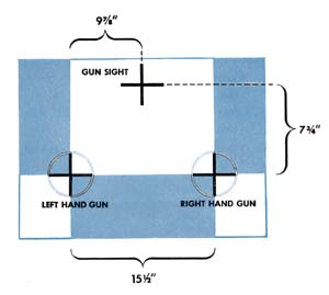
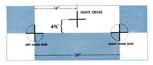
Another method of harmonization is to line up the sight and guns on a special pattern stand or template such as the one illustrated above. Set up the stand as level as possible at least 50 yards from the side of the plane. Center the guns in their mounts. Then boresight each gun on the pattern stand and center the sight on the sight cross, using the standard technique described in the Sights and Sighting Section of this manual. Both methods described here are called parallel harmonization.

Illustration of gun harmonizing

Restricted

T-41


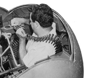
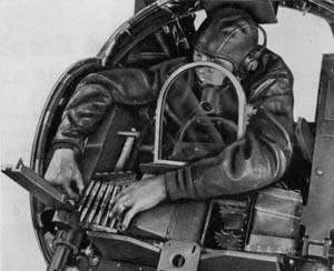
Loading Ammunition
The ammunition magazines for the Erco Tear Drop Turret are located inside the airplane and fed into the turret through the aft trunnion. To load the ammunition:

1. Carefully flake the ammunition belt down in each magazine—projectiles pointing outboard.
2. Rotate the gun carriage to the beam in azimuth for loading the guns.
3. Make sure the gun firing switches are turned off on the control panel.

4. Push the ammunition belts through the tracks until the ends extend above the track bends between the foot armor plates.
5. Drop a wire down through each booster-feed channel and tie it to the ammunition belts. Pull the ammunition belts up over the boosters to ammunition feedway of guns.
Pushing ammunition belts throught the trackRemoving empty links and cartridges

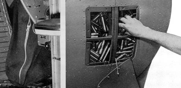
Removing Empty Links and Cartridge Cases

To remove the empty cartridge cases and links from the expended ammunition containers on either side of the seat, roll the turret a few degrees above horizontal and move the guns to either extreme in azimuth. One of the expended ammunition containers will now be in front of the entrance door. Pull cut the latching pin on the access door in the back of this container and raise the access door on top of the expended ammunition container. Reach down and push out the empty cartridge cases and links. Close the access doors and reinstall the latching pins. Run turret in other extreme azimuth position and repeat procedure.

Restricted

T-42


Pre-Flight Routine

. . . FOLLOW STEP BY STEP

PB4Y-2 airplane
1. Install barrel and oil buffer groups in the guns, leaving out the bolts and back plates.
2. Check harmonization of guns and sight by boresighting on a pattern stand or some other object 1000 or more yards away.
3. While harmonizing the guns and moving the turret by the manual azimuth and elevation hand cranks, check and make sure the clutching arrangements are working satisfactorily.
4. Make sure the bolts are assembled properly to feed from the right for the left gun and from the left for the right gun. Then install the bolts and back plates on both guns.
5. Try to rock the guns in their mounts to make sure they are securely mounted. Check to determine if the jam nuts are up tight.
6. Operate the hand charging units on the outboard side of each gun.
7. Inspect the hydraulic system and lines carefully. This should be done with and without the pump operating. If there are any leaks —report them immediately.
8. Inspect electrical leads and flexible conduits (Breezes) to determine if they are frayed or damaged.
9. Check all Cannon plugs to see if they are properly fitted and screwed up tight.
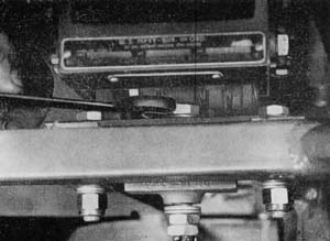
10. Check carefully to determine if there is any foreign matter on the bottom of the turret so that they will not foul the drive bands which control the azimuth movement. Keep the safety belt up while operating the turret.
11. Check oxygen connections to be sure they are tight.
12. Make sure the plexiglas windows and bulletproof glass are properly cleaned.
13.
Check for ease of operation in elevation and azimuth. Stop turret with pump running (control handles in neutral) and check for creep.
14. Check for "line knock" (air and hydraulic system) while operating the turret in all extremes. If any is noticeable, report it to the maintenance man.
15. Operate the turret in extreme elevation, depression, and azimuth to determine if the limit stops are functioning properly.
16. Insert a test light in place of the electric triggers and with the triggers depressed, swing the turret across the portions of the ship into which the guns could fire. The test light will go out in this area. With a boresighting tool, check the distances from the surface that the interrupter cuts out.
17. Turn on sight switch and rotate the sight rheostat from dim to bright to adjust the brightness of the reticle, and make sure this rheostat is working properly.
18. Test both filaments of the sight bulb to determine if they are good. If either is burned out, replace the bulb. Check for spare sight bulbs in the stowage clips over the aft corner of access door inside turret.
19. Make sure the reflector plate of the sight is clean.
20. Turn on the power, charge the guns, and then depress your safety switches—squeeze either trigger—listen for the "click" of the firing pins in the guns. Both guns should fire from either trigger at the same time, pro-

Restricted

T-43


iding that both gun selector switches are turned on. Test the other trigger by repeating the operation.
21. Put on the oxygen mask, connect it, and make sure you are getting the proper flow of oxygen. Check the regulator to determine if it is functioning correctly.
22. Plug in your headphones and microphone and test interphone system.
23. Plug in your heating suit and make sure it begins to heat.
24. Make sure the trouble lights operate. Replace any bulbs that fail to function.

2. Clear the guns by lifting the gun covers, removing the ammunition, and hand charging them twice.
3. Remove ammunition belts from feedways.
4. Open the entrance door.
5. Run the turret to 0° elevation and to a right angle from the center line of the ship, \r, azimuth. Turn off all switches.
6. . Get out of the turret.
7. Lift up the azimuth by-pass valve lever and shove the turret to its stowed position. Depress the azimuth by-pass valve lever.
8. Close the entrance door.

25. Inspect all ammunition belts for condition and proper belting.
26. Check the booster motors by tipping them towards the guns. Make sure that they cut "on" and "off" sharply without lagging.
27. Load all four ammunition magazines in the airplane. Turn off power in turret. Feed the double link through the ammunition feeds into the turret and up over the booster motor's sprockets. Place the first round into the feedway of the gun. You will not charge the guns until in the air and ordered by the plane captain.

PB4Y-2 airplane

TBF with folded wings

Before Landing
1.
Disconnect any auxiliary units that you have been using.
2. Get out of the turret.
3. Remove the ammunition can.
4. Open the access door on the bottom of the ejected link and cartridge case container on

After Landing
1. Remove all ammunition from chutes and magazines.
2. Open access door in the back of the expended ammunition containers on either side of the seat and clean out the cartridge cases and links. Relatch access door upon completing the job.
3. Field strip the guns.
4. Clean and inspect the gun receivers and detail strip the parts you have removed. Clean and check their condition.
5. Do not leave excess oil or cleaning fluid in the turret.
6. Report any malfunction of the guns or turret noted on the mission.

Restricted

T-44


Erco ball turret

ERCO Ball Turret
ERCO 250SH-2, 2A or 3

The Erco Ball Turret is the bow installation in the Navy PB4Y-1 and PB4Y-2 airplanes. It serves a double purpose in taking care of any bow attacks on the Liberator besides being used for strafing, in anti-submarine warfare. Inasmuch as this turret is of the ball type, the gunner moves with his guns and sight in elevation and azimuth as he moves his control handles. It is a relative of the Martin 250SH Bow Turret of the PBM-3 airplanes and has many points of similarity in design and action.

There are several models which for the most part are the same—the Erco 250SH-2 or 2A used in the bow position of the PB4Y-1 airplane and the Erco 250SH-3 used in PB4Y-2 airplane.

Restricted

T-45


Facts and Figures

Elevation limits

POWER
The Erco 250SH operates hydraulically on pressure built up by a hydraulic pump driven by a constant speed electric motor.

SIGHTS
Its sight is the standard Navy Mk 9 reflector sight, fully described in the introduction of this section.

ELEVATION
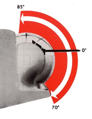
From the horizontal position the turret ball, and consequently the guns, may be depressed a maximum of 70° and elevated a maximum of 85°.

AZIMUTH
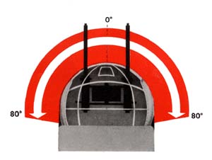
This type of turret is capable of revolving 360° in azimuth, but for the installation in the bow of the PB4Y-1 or PB4Y-2 airplanes, its motion is restricted to 80° either side of the center line of the plane.
Azimuth limits

PB4Y-2 silouette showing ball turret location

STOWING
The stowing position is 0° azimuth and 0° elevation, guns pointing straight forward.

ARMOR
The armor plate of the turret consists of three parts to protect the gunner from enemy fire and flak:
(1) 1 1/2" laminated bullet proof glass to protect his face.
(2) 1/2" armor plate in front to protect the gunner's body, no matter where his guns are pointed.
(3) 1/4" armor plate bolted to the floor to protect his feet.

Restricted

T-46


Getting In . . .
Now that you are becoming acquainted with the Erco Ball Turret, you should realize that, like all other bow turrets, it is no place to be during a take-off or landing. Your additional weight in the bow would put undue stress on the airplane, besides making the ship unbalanced; therefore, never enter the turret until the plane is in full flight.
Getting into the Erco Ball Turret is a relatively easy job if you will pursue the following steps: First of all, make sure the azimuth clutch is engaged. The small round red handle on the bottom of the turret saddle on the azimuth gear box, must be in the down position. Then make sure that the red handled elevation clutch on the back of the saddle below the right hand corner of the entrance door has not been pulled out.

Azimuth clutch handle

Never try to get into the turret if the clutches are disengaged, as the turret ball will roll under your weight. This could be very dangerous to you besides damaging the turret.
Before entering the turret, throw the main power switch to the on position. This switch is located in a junction box mounted on the left bulkhead in the Liberator's nose, almost directly under the turret. Open the entrance door in the back of the turret by turning the handle clockwise. Check the control panel, which is located front center in the turret directly above the control handles, to make sure that all the switches are off. This will prevent the turret from moving and trapping you while you are in the doorway.
With both hands grasp the bar handle installed above the entrance door. Raise both feet simultaneously and swing into the turret,

Elevation clutch handle

Restricted

T-47


placing your feet on the foot armor plates below the front magazines. Slide forward in the seat so that your head will clear the top of the door opening and swing forward to get your head inside of the turret. Close the door by a sharp pull on the bottom portion and secure the door latch by pulling down on the inner handle.

Check the door latch to see if it is secured by leaning back against it. Look through the sight and determine if you are at the proper level to see through it. If not, reach down between your legs and grasp the seat adjustment lever so that you may raise or lower the seat. Fasten the safety belt as you will need it. You are now ready to operate the turret.

Entering turretSeat adjustment lever
OPERATING THE TURRET
Control panel

. . . Where to Find the Controls
. . . How to Use Them


The control panel, which you checked before entering, is above the control handles directly in front of you. All the switches which will put the turret to work are on the control panel. Be sure to turn them on in the proper order.

First, turn the motor circuit breaker (A) switch to the on position. Then, push and release the power switch button (B). A red indicator light (C) on the turret control panel should light up, showing you that the power is on in the turret.

To start the pump motor use the bottom edges of your hands to press down the two safety

Restricted

T-48


switches. When the motor is running, the handles will automatically go to neutral position. For this reason it is best to press the safety switches down before grasping the hand grips of the control handles.
If this is done, the control handles will move to neutral position without moving the turret. If the control handles are held in any other position than neutral and the safety switches are closed, the motor will start, causing immediate and possibly violent motion of the turret. Either safety switch will put the motor in operation. Depressing the safety switches also turns on the sight and provides power to the booster motors so that they will operate when guns are fired.
To adjust the brightness of the sight to lighting conditions use one hand to hold the control handles, keeping the safety switch depressed, and turn the sight rheostat with the other hand. To operate the turret turn the handles in the direction you desire the turret to move. For azimuth (right or left) the control handles are operated exactly like those of a bicycle. For elevation, move the upper part of the handgrips backward, and for depression, move the top portion of the control handles forward. Don't jerk the controls—move them smoothly and deliberately.

Charging handle

charging handle of one gun with both hands, one above the other, and give a quick, hard pull back. Then release the handle smartly and let it slide forward by itself. Repeat the procedure for the other gun.

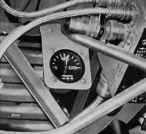
At the left of the control panel is the hydraulic pressure gauge. As soon as the pump is operating, check to see if it reads the desired At the left of the control panel is the hydraulic pressure gauge. As soon as the pump is operating, check to see if it reads the desired 1150 Ibs. pressure. While operating the turret, check this gauge from time to time to see if the proper pressure is maintained. Directly under your index fingers on both control handles are the triggers. Either trigger will fire both guns.
On each side of you at shoulder level are the levers for hand-charging the guns. Grasp the lbs. pressure. While operating the turret, check this gauge from time to time to see if the proper pressure is maintained. Directly under your index fingers on both control handles are the triggers. Either trigger will fire both guns.
On each side of you at shoulder level are the levers for hand-charging the guns. Grasp the

Hydraulic pressure gauge

Restricted

T-49


Using the Auxiliary Units

The oxygen system in the turret is a complete self-contained unit, consisting of two oxygen cylinders and a regulator, which are located in the locker in the entrance door behind the back-rest. A hose connects the regulator to the oxygen mask. In the older type turrets, three cannisters are provided in individual brackets—one in the entrance door and one on each side magazine. Newer turrets are provided with oxygen equipment which makes the cannisters unnecessary.

Auxiliary units

The heated suit cord is plugged into an outlet on the left side of the control panel and is turned on by a suit switch (D) on the same panel. A camera is mounted in front and a little below the bulletproof glass face plate. To put the camera into operation it is necessary to have the camera heat (E) and camera trigger (F) switches in the on position on the control panel and either of the safety switches and either of the trigger switches depressed. The interphone jack box is located on a bracket next to your right knee. This is where you plug in the jacks for your headphones and throat microphone. Installed on the front of the box is a push-to-talk button which operates the interphone system when you wish to speak.
A light switch (G) on the control panel operates an extension type trouble light mounted on the right side of the ball structure next to your right knee.
In the event that the electric drive motor fails, the turret can still be operated by working the emergency hand pump. Work the hand pump with the right hand and hold the left hand grip of the control handles turned in the direction you desire the turret to move. This hand pump will facilitate harmonizing the guns and sight when a small amount of carefully controlled movement is desired. In the latest turrets an auxiliary foot firing mechanism is provided if the power to the guns fail. To put it into operation release the red safety catch over your right foot; then depress either red bar found above your feet and the guns will fire.

Restricted

T-50


Getting Out
When you get out of the turret—before landing, if you are on a flight—be as careful as you were when getting in.
Remember that the doors can trap a careless gunner on the way out as well as on the way in. First, move the guns to stowing position—guns at zero elevation and zero azimuth; then, turn off all switches in the turret.
Disconnect any auxiliary units you have been using.
Reach around and open the door. Ease your body out of the turret by grasping the bar handles installed in the airplane above the entrance door.


Removing the plastic canopy

Emergency Exit

Removing the plastic canopy
In the event that it is necessary for you to get out of the turret in a hurry, an emergency exit is made possible by removing the plastic canopy. This is done by releasing the latch off all switches in the turret. Disconnect any auxiliary units you have been using. Reach around and open the door. Ease your
mechanisms in the upper structure of the turret. Pull out the four red painted handles and push the canopy up and forward with both hands.


The Sight

The Navy Mk 9 sight fits into the gunsight bracket directly behind the laminated bulletproof glass. To adjust the sight as may be sometimes necessary in harmonizing it with the guns, make the adjustments on the sight head. For full instructions in making these adjustments see the section on the Mk 9 sight in the general introduction of this section.
MK 9 sight.

Restricted

T-51


Preparing the Turret for Combat

The preceding pages explained how to get in, operate, and get out of the Erco Ball Turret. From this information you could take over and operate the turret in combat. If you specialize on the Erco, however, that will be only part of your job. Other duties such as adjusting the sight and guns, and loading the ammunition for a mission, are explained in the following pages.

Adjusting the Guns

Adjusting the mounting screws

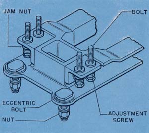
The guns are mounted in the Erco to feed from the inside; the right gun feeds from the left and the left gun feeds from the right. Each gun is bolted into a Bell Mount Adapter and adjusted in elevation by means of adjustment screws on both sides of the rear gun mount support. All four of these screws must be set with the jam nuts to secure the gun in position. The guns are adjusted horizontally in either direction by turning the eccentric bolts in the rear of the gun mount supports. The two rear bolts must be set tight with their elastic stop nuts in order to secure the guns in position. The front bolts should be loose enough to allow all boresight-ing to be done from the rear.
Bell mount adapter
Tightening the rear bolts

Restricted

T-52


Harmonizing the Guns and Sight

There are a number of ways to harmonize the guns and sight of the Erco Ball Turret. The exact procedure will be defined by the Squadron Gunnery Officer. A handy method is to line up the sight and boresight the guns on some small object, such as a tree or chimney, at least 1,000 yards from the plane. To do that remove the back plates and bolts from both guns—or use a boresight tool so that you can look through the gun barrels without removing the parts. Turn the turret until the guns point at the object you have selected.
on is exactly in the center of each gun bore. Sometimes the amount of adjustment in the rear mounts of the guns may not be large enough to bring the guns to bear on the object. In that case, boresight each gun on the object selected. Then make the necessary adjustment on the sight head to line up the sight dot on the same object.
Another method of harmonization is to line up the sight and guns on a special pattern stand or template, such as the one illustrated here. Set up the stand as level as possible at least
Boreshight templete
Then line up the sight, using the emergency hand pump to move the turret until the dot of the sight is squarely on the object. Don't move the turret again. Now boresight through each gun barrel to line up each gun. Adjust each gun by its rear mount adjustment screws and bolts until the spot the sight is centered
50 yards in front of the plane. Center the guns in their mounts. Then boresight each gun on the pattern stand and center the sight on the sight cross using the standard technique described in the Sights and Sighting Section of this manual. Both methods described here are parallel harmonization.
Illustration of gun harmonizing

Restricted

T-53


Left and right cartrigde feedways
Loading Ammunition
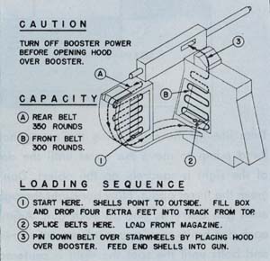
Each gun in the Erco Ball Turret has two magazines, one in the side beneath the gun which it feeds, and the other at the front of the turret ball. In all, the total capacity of the four magazines is 1200 rounds.
To load the magazines:
1. Get into the turret, but do not close the entrance door.
2. Pull out the pins on the access doors of all four magazines, and slide the doors off.
Capacity and loading sequence
Loading cartridge belt


3. Remove the transparent ammunition track covers.
4. Fill either side magazine by passing the ammunition belt over your shoulder and down through the top of the magazine.

Restricted

T-54


single link first, projectiles pointing outboard. Flake the belt down until the magazine is full.
5. Pass the free end of the ammunition belt down through the ammunition track at the rear of the side magazine and up around the rollers to the bottom of the corresponding front magazine. About six feet of belted ammunition will be required to reach the front magazine.
6. Fill the corresponding front magazine by passing the ammunition belt over your shoulder and down through the top of the magazine, single link first, projectiles point ing forward.
7. Splice the ends of the ammunition belts of the front and side magazines.
8. Flake down the ammunition belt in the front magazine.
9. Run the end of the ammunition belt up over

Loading cartrigde belt into right gun

the booster sprockets. Lift the gun cover and insert the double link end of the belt into the gun.
10.. Repeat the procedure for the other side.
11. Replace magazine access doors and transparent ammunition track covers.

Both guns loaded

Restricted

T-55


Removal of Empty
Cartridge Cases and Links

The empty cartridge cases are removed from the empty cartridge case chamber in the front of the turret through an access door located on the outside lower front portion of the turret bail. After cleaning out this chamber, be sure to replace the access door securely. The empty links drop into canvas bags held under the empty link chute on each gun. These bags are equipped with zipper openers to provide easy removal of the links.
Removing empty links
Pre-Flight Routine . . . Follow Step by Step
PB4Y-2 airplane


1.
Install the barrel and oil buffer groups in the guns, leaving out the bolts and back plates.
2. Check the harmonization of the guns and sight by boresighting on a template or some small object 1000 or more yards away.
3. While you are harmonizing the guns and moving the turret by the emergency hand pump, make sure the hand pump is operating properly.


Restricted

T-56


4. Make certain that the bolts are assembled properly to feed from the right for the left gun, and from the left for the right gun. Install the bolts and slide the back plates on both guns.
5. Try to rock the guns in their mounts to make sure they are securely mounted. Check to determine if the jam nuts are up tight.
6. Operate the hand charging handles on the inboard side of each gun..
7. Inspect the hydraulic system and lines carefully. This should be done with and without the pump operating. If there are any leaks —report them immediately.
8. Inspect electrical leads and flexible conduits (Breezes) to determine if they are frayed or damaged.
9. Check all Cannon plugs to see if they are properly fitted and screwed up tight.
10. Put on the oxygen mask, connect it, and make sure you are getting a flow of oxygen. Check the gauge to make sure there is the proper pressure as determined by your crew chief.
11. Check oxygen connections to be sure they are tight.
12. Make sure the plexiglas dome and bulletproof glass are properly secured and cleaned.
13. Operate the turret to determine if the pressure gauge reads the required 1150 lbs. pressure.
14. Check for ease of operation in elevation and azimuth. Stop turret with pump running, (control handles in neutral). Check for creep.
15. Check for "line knock" (air in hydraulic system) while operating turret in all extremes. If any is noticeable, report it to the maintenance man.
16. Operate the turret in all extremes to determine if the limit stops are properly functioning.
17. Turn on the sight switch and rotate the sight rheostat from dim to bright to adjust the brightness of the reticle, and make sure the rheostat is working properly.
18. Test both filaments to make sure the sight bulb is good. If either is burned out, replace the sight bulb.
19. Make sure the reflector plate of the hood assembly on the sight is clean.
20. Turn on the power and charge the guns. Then, depress the safety switch and squeeze either trigger and listen for the "click" as the firing pins in the guns release. Both guns should fire from either trigger at the same time. Test both triggers by repeating the operation.
21. Plug in your headphones and microphone to test if your crew mates can hear you and if you can hear them.
22 Plug in your heating suit and make sure that it begins to heat.
23. Make certain that the trouble light operates. Pull the light out of its cord, making sure the retractable reel is working properly.
24. Inspect all ammunition belts to determine if the rounds are in good condition and properly belted. Check booster motors by tipping them toward the guns. Make sure that they cut on and off sharply without lag.
25. Load all four ammunition magazines. Feed the double link ends up over the booster motors' sprockets and press the first round into the feedway of each gun. You will not charge the guns until you are in the air and so ordered by your plane captain.
26. Make a last visual check of the whole turret.

Restricted

T-57


Before Landing


1. Run the turret into its stowing position, zero elevation and zero azimuth, guns pointing straight forward.
2. Clear the guns by raising the gun covers, removing the ammunition, and hand charging the guns twice.
3. Remove all ammunition from feedway. Check all switches and make sure they are off.
4. Get out of the turret and close and latch the door.

PB4Y-2 airplane

PB4Y-2 airplane
After Landing
1.
Remove all ammunition from chutes and magazines. Open access door in front lower

portion of the ball and clean out expended cartridge cases. Replace this access door securely on completing the job. Remove used links from canvas bag held under the empty link chute on each gun. A zipper is provided to open the bag.
2. Field strip the guns by removing their working parts.
3. Clean and inspect the gun receivers, then detail strip the parts you have removed from the guns, cleaning them and making a thorough check of their condition. Do not leave excess oil or cleaning fluid in the turret.
4. Report any malfunction of turret or guns noted on the mission.

Restricted

T-58


Previous Section - Table of Contents - Next Section

Transcribed and formatted by Thomas Wildenberg for the HyperWar Foundation