
CHAPTER III
Capabilities of Radar
A. Introduction: Classes of equipment; requirements of a radar,
B. Applications of radar and associated equipment: Air search; height-finding and low-angle search; surface search; equipment for submarines; fire control; repeater PPI; recognition equipment; radar beacons,
C. Interpretation of echoes: General; characteristics of pips; type of indicator.
D. Characteristics of shipborne radar: Radar installations in ships; performance and operational data; operating console photographs. |
A. INTRODUCTION
Radar equipment is capable of detecting the presence of objects in the air and on the surface and of measuring their range and bearing. Some of the sets that have been produced are capable of measuring directly the position angle of aircraft, while others permit an estimate of elevation to be made by reference to a calibration chart.
Three general classes of radar equipment have been developed:
(1) Search or detecting equipment.
(2) Fire control equipment.
(3) Recognition and beacon equipment.
Each of these classes can be subdivided into several types of equipment that have been produced to perform well one function. For example, search equipment is available for air search, height-finding and low-angle search, and surface search. Radar equipment for submarines is primarily detecting equipment, but the surface search radar is capable of determining range and bearing accurately enough to control torpedo fire. Since submarine radar is designed for a specialized application, it will be considered separately from other search equipment.
Fire control radar, which is capable of a rather high order of accuracy, has been developed for use with all types of gun batteries. If the required accuracy cannot be obtained by radar alone, the equipment may be used lor the control of searchlights to permit optical control of gunfire. The Navy has no radar equipment built specifically for searchlight control, but it is reported that the Japs are using radar designed for this purpose.
Since radar equipment alone is not capable of distinguishing friendly from enemy vessels, auxiliary equipment has been produced to aid in this vital function. This equipment is called IFF, which stands for "Identification, Friend or Foe." A similar type of accessory equipment is the radar beacon or "Racon."
In many cases the uses of a given search radar can be extended if the indication of the echoes can be displayed simultaneously in several locations. To permit this kind of operation, several types of repeater plan position indicators (RPPI) have been produced.
The requirements of each of the several types of radar differ widely. An air search radar must measure range and bearing to only a fair degree of precision since its primary function is warning of the presence of aircraft at extreme ranges. Radar used for aircraft control should be capable of determining range, bearing, and altitude with good accuracy, and it must be capable of resolving targets that are close together in order to control successfully the intercepting planes. Air search radar is used in conjunction with the height-finding and low-angle search radar for the control of aircraft. Surface search radar must determine range and bearing of targets on the surface with moderate precision, and must have sufficiently high resolution to enable ships within firing range to show as separate targets on the radar indicator so that targets can be indicated to fire control radars. Fire control radar must determine range, bearing, and altitude with the greatest precision practical in order to produce accurate gunfire, and the radar should be capable of resolving two very close targets so that shell splashes can be distinguished from the target proper, allowing the guns to be spotted on to the target.
As a result of these varying requirements, the several types of radar equipment have fundamentally different characteristics which allow them to perform their primary functions best, generally at the expense of other functions. Thus, in present air search radar, some sacrifice is made of effective range at low altitudes and degree of resolution between targets in order to enable the set to detect aircraft at very long ranges. Surface search radar is able to detect both vessels on the surface of the ocean and low flying planes, but it is unable to detect aircraft at high altitudes.
--21--
B. APPLICATIONS OF RADAR AND ASSOCIATED EQUIPMENT
Although each radar equipment is designed for one primary function, the uses to which sets may be put overlap to some extent. Listed below are many of the applications of radar equipment. Other applications will undoubtedly be found as more operating experience is gained and as newer sets with enhanced capabilities become available in the Fleet.
1. Air search radar equipment.--Navy types: SA, SC, SK, SR, SX.
-
Warns of approaching aircraft before they can be sighted visually, so that:
-
The direction from which attack may develop may be indicated.
-
Fighters may be flown off in time if an air attack is imminent and a carrier is in company.
-
A fighter escort may be called for in sufficient time if no carrier is in company.
-
AA defenses may be brought to the proper degree of readiness in sufficient time.
-
Allows the constant observation of the movements of enemy aircraft, once detected, and the direction of own fighter planes to a position suitable for interception.
-
Warns of the presence of enemy surface craft that are beyond the visible range at night or during conditions of poor visibility, so that correct disposition of the fleet may be made to meet an attack, or preparations made to attack the enemy by surprise. It must be remembered that this is the primary function of the surface search radar.
-
Provides security against night attack, attacks during conditions of poor visibility, or from behind a smoke screen.
-
Scouting.
-
Ranges on land up to 150 to 250 miles.
-
Obtains bearings, but not ranges, on other ships having radar on the same frequency at distances in excess of the maximum ranges from which echoes can be received. This ability is of especial value in making a rendezvous with a convoy.
2. Height-finding and low-angle search radar equipment. Navy Types: SM, SP, SX.
-
Obtains accurate range, bearing, and altitude data on enemy planes to assist in the direction of own fighter planes to a position suitable for interception.
-
Permits continuous control of own fighter planes while they are within range of the radar.
-
Detects low-flying aircraft.
-
Acts as high-power surface-search radar when no air attack is imminent.
-
Obtains meteorological data by observing the movements of balloons equipped with radar reflectors. The ability of the height-finding and low-angle search radar to measure position angle as well as range and bearing allows it to provide a more useful track on the balloon than can be obtained with an air-search radar.
-
Detects the presence and extent of thunderstorms and other severe weather disturbances. This enables aircraft carriers to maneuver to the most favorable area for launching or receiving planes, and to vector planes around the storm area.
-
Ranges on distant land up to 80 miles.
3. Surface search radar equipment. Navy Types: SF, SG, SL, SN, SO, SQ, SU.
-
Warns of the presence of enemy surface craft that are beyond the visible range at night or during conditions of poor visibility so that the correct disposition of the Fleet may be made to meet an attack, or preparations made to attack the enemy by surprise. Radar will not detect ships beyond visible range on clear days.
-
Coaches fire control radar to enable it to get on target quickly.
-
Provides security against attack at night, during conditions of poor visibility, or from behind a smoke screen.
-
Scouting.
-
Obtains range and bearing on prominent landmarks and buoys as an aid to piloting, especially at night and in conditions of poor visibility.
-
Facilitates station keeping, especially at night and in poor visibility.
-
Acts as auxiliary fire control radar in conjunction with a precision PPI.
-
Indicates spots on shell splashes in both range and bearing, especially in ships that are not equipped with a fire control radar such as the Mark 8.
-
Detects life boats and life rafts at short ranges when they are equipped with corner reflectors. There is some indication that floating objects, wreckage, and even men in the water can be detected at short ranges, so that surface search radar may be used to some extent in rescue operations.
-
Obtains bearings, but not ranges, on other ships equipped with radar operating on the same frequency at distances in excess of the maximum from which echoes can be received.
-
Ranges on land up to 50 miles.
4. Submarine Radar Equipment. Navy Types: SD, SJ, SS, ST, SV.
-
Provides warning of presence of aircraft and surface vessels either while submarine is surfaced or submerged to periscope depth.
--22--
-
Obtains accurate ranges, with optical bearings, on surface vessels while submarine is submerged to periscope depth, for use in torpedo control.
-
Obtains accurate range and bearing data for torpedo control while submarine is surfaced, especially at night and in conditions of poor visibility.
-
Obtains range and bearing on prominent landmarks and buoys as an aid to piloting.
-
Permits very directional, secure communications between submarines within at least 30,000 yards.
5. Fire Control Radar Equipment. Navy types: Main battery--Mark 3, Mark 8, Mark 13. Secondary battery--Mark 4, Mark 12, Mark 22. Heavy machine guns--Mark 26, Mark 28, Mark 29, Mark 34.
-
Supplies smooth, accurate ranges and fairly accurate bearings and position angles to the computer so that a solution to the fire control problem may be obtained more quickly than by optical means.
-
Indicates spots in both range and deflection by ranging on shell splashes. At short ranges it is possible to follow the projectile on the radar throughout its entire flight.
-
Can be used for calibrating anti-aircraft projectile fuses by comparing the range of the burst with the fuse setting.
-
Supplies data for the direction of starshell or searchlight illumination.
-
Obtains meteorological data by observing the movements of balloons equipped with radar reflectors.
-
Detects low-flying aircraft.
-
Supplies useful tactical data such as the position of other ships in own force, and greatly facilitates station keeping at night or in poor visibility.
-
Detects surface craft in the event of failure of the surface search radar.
-
Ranges on land up to 75 miles.
6. Repeater PPI Equipment.
-
Standard Repeater PPI. Navy types: VC, VD, VE, VH, VJ, VK.
-
Reproduces any desired PPI information at several selected locations remote from the radar room.
-
Permits a given radar to be used in two or more applications simultaneously, such as station keeping and surface searching. This is especially true in the case of a system which is equipped with Sensitivity-Time Control (STC) and Instantaneous Automatic Volume Control (IAVC) because these features permit close-in echoes to be seen just as clearly as those at long range.
-
In the presence of enemy jamming, the selector switch permits a rapid check of available radar frequencies to determine which is the least affected.
-
Provides a means of revealing enemy deception by comparing the effect on several radars.
-
Provides direct assistance in piloting and station keeping by showing the PPI indication of the surface search radar on the bridge.
-
Provides, with the use of attachments that produce expanded sweeps, a more desirable presentation for use in controlling aircraft interceptions than is possible on many radar PPIs.
-
Precision Repeater PPI Equipment. Navy type VF.
-
Permits close observation of a small sector while the radar proper surveys the whole 360°.
-
Obtains from surface search radar range data to an accuracy comparable to that from fire control radar, and bearing data that may be slightly more accurate than that obtained from the radar.
-
Expands a small sector to cover a large area so that it is feasible to spot shell splashes in both range and deflection with reasonable accuracy.
-
Enables a ship to keep on station within very small limits.
-
Provides a means for transmitting range and bearing data for use in target indication.
-
Projection Repeater PPI Equipment. Navy type VG.
-
Eliminates time lag in plotting of radardata.
-
Provides excellent surface on which to maintain a surface summary plot.
-
Provides large surface which can be used as a plotting table for air plot or surface plot.
-
Reduces plotting errors by simplifying plotting.
7. Recognition equipment for use with radar (IFF). Navy types: ABK, ABF, AN/APX-1, AN/APX-2, BK, BL, BM, BN, BO.
-
Identifies on the radar screen the echoes from friendly aircraft and ships by returning a coded response during a 12-second period.
-
Indicates the range and bearing of friendly aircraft at distances in excess of the maximum from which echoes can be obtained.
-
Identifies to the Fighter Director Officer which echoes out of a group are the fighters over which he has control. This identification is made on the G band and is instantaneous and uncoded.
-
Acts as a beacon, using a code selected for the purpose, to indicate contact with the enemy.
-
Acts as a beacon on which aircraft can home.
--23--
-
Indicates distress by producing on the radar screen an exceptionally wide signal. This signal should be used only by aircraft and ships that are in distress such that they are unlikely to be able to return to their base, or by vessels standing by another in distress.
-
Indicates, by use of coded response, the role in which a particular craft is employed. For example: during an operation it might be desirable to allot different codes to high cover fighters, low cover fighters, bombers, reconnaissance aircraft, and ships.
-
Provides navigational fix for a ship by a shore station observing range and bearing of IFF response.
-
Allows radar to follow friendly planes through null areas in antenna pattern or through severe clutter like that produced by hilly terrain.
8. Radar Beacon Equipment--Racons. Navy types: YH, YJ, AN/CPN-3, AN/CPN-6, AN/CPN-8, Mk 1, Mk 2, Mk 4, Mk 5.
-
Guides aircraft back to ship or shore base.
-
Provides accurate navigational fixes.
-
Provides point of aim for shore bombardment.
-
Provides a small, isolated target for use in aligning radar antenna.
-
Assists in a landing by helping to vector landing craft through restricted waters.
-
May be useful in the presence of jamming since a powerful signal slightly off radar frequency is returned.
C. INTERPRETATION OF ECHOES
1. General.
The pips that appear on a radar indicator show only the presence of targets within the field of view of the radar. The position of the echo signals on the screen indicates range and bearing. Beyond this simple, measurable information the pips do not, of themselves, reveal any further data. However, there are small variations in the character of the echo signal that indicate, to some extent, the nature of the target. These variations are either imperceptible or meaningless to inexperienced observers.
After long experience in looking at a radar indicator, a good operator is able to interpret what he sees reliably, and often with a surprising degree of detail. To an untrained operator, the echo from one ship looks like the echo from any other ship. However, with proper training, the operator will often be able to estimate the type of ship detected. In fact, it has been reported that after the same group of ships had operated together for a long time, one radar operator could name several of the ships simply by observing the characteristics of their echoes.
2. Characteristics of Pips.
In general, there are four characteristics of pips that may give useful information:
-
Size of pip.
-
Shape of pip.
-
Fading or fluctuation in height.
-
Movement in range and bearing.
The operator will be able to distinguish between land, airplanes, and ships, and perhaps to estimate both the type and number of targets in a group by observing these characteristics of the echo signals.
The size of the pip depends on so many factors that reliance cannot be put in observation of this factor alone to estimate the type of target. However, since the size of the echo returned from a target at a given range depends on the magnitude of the target, the size of the echo may often be useful in indicating which targets of a group are large.
Because large targets can be detected at longer range than small ones, the range of first pick-up may be used as a basis for estimating the type of target detected. This estimate is complicated by the fact that several small targets in a group may be detected at a greater range than a single large target, and by the fact that target angle affects the size of the echo to some extent. However, at ranges greater than 15 to 20 miles, most ships are hull down so that the effect of target angle is negligible because the echo is returned from the mast and superstructure.
The shape of the echo is very useful as an indication of how many targets are in a group. In a formation of many planes, for example, the echo will spread over a long range, and on the A scope it will have many peaks. On a PPI scope, the shape and size of an echo may be such that the target could not be anything other than a cloud or a storm.
The amount and peculiarities of the fading of an echo pip often indicate the nature of the target. The echo returned from an airplane flutters rapidly and irregularly. This characteristic alone is often sufficient to enable the operator to select airplane echoes from others on his scope. A large ship generally produces a pip that bobs up and down slowly, while the echo from a small vessel flutters rapidly, especially in a rough sea. Land echoes are usually fairly steady, but when the sea is rough, some land echoes may flutter.
Plotting radar contacts over a period of time enables the course and speed of the target to be determined. If the speed is greater than 80 knots, the target must be an airplane, for even the relative speed of surface targets rarely exceeds 60 knots. Correlation of speed with the rate of flutter and the other characteristics of a pip frequently enables an estimate
--24--
to be made of the type of target. For example, a small echo that flutters violently and quickly, and which has a speed of 40 knots is probably a PT boat.
3. Type of Indicator.
Because the antenna must rotate continuously to produce a PPI presentation, the beam is never on a target long enough to allow the flutter of the echo to be apparent. The limiting of the echo signals that takes place before they are applied to the PPI tube removes most of the flutter that would tend to show. Consequently, practically no flutter shows on a PPI screen, so that this characteristic cannot be observed as an aid in interpreting the echo.
This disadvantage of the PPI scope is offset by the fact that it shows both range and bearing, enabling the disposition of a group of targets to be shown clearly on the screen. If the targets are separated sufficiently to allow the radar to resolve their echoes into separate pips, the number of targets is immediately apparent.
The targets, however, will often be so close together in range and bearing that they will show as a single bright spot on a PPI. In this case, the A scope permits a more reliable interpretation to be put on the pip because the number of peaks and the type of flutter can be observed. In order to observe these characteristics, the radar antenna must be stopped for thirty seconds or longer. This stoppage is very undesirable from the point of view of searching. If the antenna is frequently stopped for prolonged inspections of pips, serious damage may be inflicted by undetected enemy planes.
An expanded sweep spreads out the echoes, making it easier to interpret the pips accurately, since minor variations are easier to see. Thus an expanded sweep is advantageous not only because of the improved resolution possible, but also because of the more reliable interpretation that can be put on the echoes. This advantage applies equally to type A, type B and type PPI presentations.
D. CHARACTERISTICS OF SHIPBORNE RADARS
A knowledge of the operating characteristics of a particular radar equipment is necessary before either the capabilities or the limitations of the set can be appreciated. Therefore, some of the characteristics of radars that are in use and of radars soon to be available to the Fleet are presented in the following pages. Photographs of several types of naval vessels are included in order to indicate the locations of the antennas of as many of the current radars as possible. Not all types of ships are shown since those included illustrate both the typical placement of radar antennas and the complement of radars on the major classes of combatant vessels, but the photographs do not neces-
sarily show the latest type allowances. The ships, and the radars normally installed on board them, are divided into three broad classes: large ships, small ships and auxiliaries, and submarines. A tabulation of the characteristics of the radars used in each of these classes is presented following the pictures of the ships. In the cases of duplication between two of these rather arbitrary classifications, as the SC-2, SG, and Mark 4 radars for example, the characteristics are included only once.
The characteristics of each radar are compiled on a single sheet. The data given for each set include: the model designation, the primary purpose, the frequency band, the antenna beam width, the types of indicator presentations used and the range scales provided, and the best available figures on the accuracy and resolution of the set. No data are given on the so-called maximum reliable range because of the rather great inconsistencies that appear in the reported figures. Until relatively recently, no absolute criterion has been available to the Fleet for judging the level of performance of a radar. Therefore, the reported maximum ranges have little meaning without their being qualified by this figure. However, with the wider use of echo boxes by the Fleet, it is expected that the radars will be more likely to be maintained at peak performance, so that this large variable will be nearly eliminated from reported ranges. It has been very convincingly demonstrated that the use of a "standard" target is by no means a reliable measure of performance (see Figure 100). In addition to the varying performance level, radar ranges are very greatly affected by conditions of propagation. In many cases atmospheric conditions exist which extend radar range far beyond the line of sight by trapping the radar pulses in a duct which guides them over the horizon and guides the echoes back to the antenna. In still other cases, the atmosphere can bend the path of the radar pulses upward so that surface coverage is markedly reduced. The weather conditions which cause these phenomena are detectable only by exhaustive meteorological soundings which are beyond the scope of the forces afloat. Since neither the true level of performance nor the existence of non-standard propagation is reported as such with the ranges obtained, the data available hardly form the basis for stating the reliable maximum ranges that can be expected with a given radar installation.
It will be noted that in many cases several models of radar are grouped together on one sheet, as the SC-2, SC-3, and SC-4. This grouping indicates that the operational characteristics of the sets in question are almost identical, although there may be some differences in the physical appearance of the sets or minor changes in the electrical circuits. The radio frequency
--25--
on which the set operates is stated as a letter because of security requirements.
An average figure is given for both the horizontal and vertical beam widths of the antenna. Not every SC-2 for example, has a horizontal beam width of exactly 20°, because it is impossible to build absolutely identical antennas and because the pattern is affected by the place in which the antenna is installed and by the frequency on which the set is operated. Thus the figures given indicate the approximate dimensions of the antenna beam of the type of radar in question, but not the precise shape of the beam of any particular set. Knowledge of the antenna pattern forms the basis for estimating the bearing resolution and it gives some indication of the possible bearing accuracy.
The types of indicator presentations are mentioned along with the range scales available on each type of indicator. These data should be helpful in appreciating both the range accuracy and the range resolution of which the set is capable. A photograph of the radar operating position is included as a means of promoting familiarization with the equipment.
Figures are presented to indicate the accuracy of the determination of range, bearing, and position angle or altitude for each set, even though it is well known that a single figure cannot truly state the accuracy of the set. There are properties inherent in a radar that limit the precision with which data can be measured.
If only these factors are considered, a very optimistic picture of the accuracy of a radar will be obtained. Additional limitations imposed by operating conditions may reduce radar accuracy considerably. For example, if both the target and the radar are absolutely stationary at the manufacturing plant, it can be demonstrated that the bearing of the target can be determined repeatedly by relatively unskilled operators within a margin of error of perhaps 2 mils. The manufacturer might then conclude that the bearing accuracy of his equipment is ± 1 mil. However, when this radar is taken to sea, where the radar is far from absolutely stationary and the target may be an aircraft flying at 300 knots, even the most highly skilled operator cannot keep the radar beam on the target well enough to determine bearing closer than perhaps ½°. Many other factors, of course, influence accuracy, so that stating single figures for accuracy may be very misleading. The figures given are intended to serve as guides, and in general they apply to the most expanded type of presentation available.
Resolution, like accuracy, depends on many factors, so that it cannot be stated exactly by a single figure. The figures shown on the illustrations are for the shortest range scale and for the type A scope in the case of search radars, unless otherwise indicated in the captions. The factors that affect resolution are discussed in Chapter V.
--26--
RADAR INSTALLATIONS ON LARGE SHIPS

Figure 19--Battleship (BB).

Figure 20--Large cruiser (CB).

Figure 21--Light cruiser (CL).
--27--
RADAR INSTALLATIONS ON LARGE SHIPS

Figure 22--Antiaircraft cruiser (CL).

Figure 23--Aircraft carrier (CV).

Figure 24--Auxiliary aircraft carrier (CVE).

Figure 25--Aircraft carrier--small (CVL).
--28--
MODELS SC-2, SC-3, SC-4, SK, SK-2
| PURPOSE--Air search |
| FREQUENCY BAND--P |
| ANTENNA BEAM WIDTH--: |
| |
|
SC |
SK |
| |
Horizontal |
20° |
20° |
| |
Vertical |
60° |
20° |
| PULSE DURATION: 5 microseconds |
| ACCURACY: |
| |
Range, ± 1 50 yards on short range scale |
| |
Bearing, ± 3° |
| |
Altitude, ± 2,000 feet with calibrated fade chart |
| INDICATOR: |
|
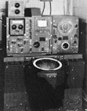
Figure 26--SK operating position. |
| Type scope |
Range scales |
| SC-2, SK A |
15, 75, 375 mi. |
| SC-3, SC-4, SK-2 A |
20, 80, 400 mi. |
| 12" PPI |
20, 75, 200 mi. |
| MINIMUM RANGE: 1,200 yards |

Figure 27--Approximate resolution on short range scale.
--29--
MODELS SG-a, SG-1
| PURPOSE--Surface search |
| FREQUENCY BAND--S |
| ANTENNA BEAM WIDTH--: |
| |
Horizontal 5.6° |
| |
Vertical, 15° |
| MINIMUM RANGE: 600 yards |
| ACCURACY: |
| |
Range, ± 200 yards on 15,000-yard range scale |
| |
Bearing, ± 2° |
| |
Altitude, not indicated |
| PULSE DURATION: 2 microseconds |
|
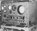
Figure 28--SG operating position. |
| INDICATOR: |
| |
Type scope |
Range scales |
| |
A |
15,000; 75,000 yards |
| |
9" PPI |
15,000; 75,000 yards |
NOTE: Modernization (Change No. 50)
provides 7" PPI
instead of 9" andn expansion of the A scope from step. |

Figure 29--Approximate resolution on short range scale.
--30--
MODELS SG-3, SG-4
| PURPOSE--Surface search |
|
PULSE DURATION: 0.3 or 1¼ microseconds |
| FREQUENCY BAND--S |
|
INDICATOR: |
| |
|
Type scope |
Range scales |
| ANTENNA BEAM WIDTH--: |
|
|
A |
4, 10, 20, 80, 400 mi. |
| |
|
SG-3 |
SG-4 |
|
|
5" PPI |
4, 10, 20, 80, 200 mi, |
| |
Horizontal |
3° |
3° |
|
|
R |
5,000 yards |
| |
Vertical |
13° |
6.5° |
|
MINIMUM RANGE: 200 yards |
| NOTE: SG-4 antenna is stabilized; SG-3 antenna is not. |
| |
ACCURACY: |
| |
Range, ± 100 yards on 20-mile range scale |
| |
Bearing, ± 3/4° |
| |
Altitude, no indication |

Figure 30--Approximate resolution on 20-mile scale.
--31--
MODEL SM
| PURPOSE--Low-angle search and height finding |
| FREQUENCY BAND--S |
| ANTENNA BEAM WIDTH--: |
| |
|
Wobbler Off |
Wobbler On |
| |
Horizontal |
2.5° |
4° |
| |
Vertical |
3° |
4.5° |
| NOTE: Antenna may be elevated over a range of -3° to +75°; antenna is stabilized. |
| PULSE DURATION: 1 microsecond |
| ACCURACY: |
| |
Range, ± 200 yards or ± ¼% of range scale, whichever is larger. |
| |
Bearing, ± ½° with wobbler (conical scanning) on. |
| |
Altitude, ± ½° above 3.5° position angle, with wobbler on. |
| INDICATOR: |
|
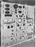
Figure 31--SM main console. |
| |
Type scope |
Range scales |
| |
A |
80 miles |
| |
7" PPI |
10, 50, 80 miles |
| |
R |
4,000 yards |
| Position angle indicated on dial. |
| Altitude in
feet automatically computed and shown on meter. Correct alignment in bearing and elevation shown on crossed-pointer meter. |
| MINIMUM RANGE: 600 yards |

Figure 32--Approximate resolution at medium range.
--32--
MODEL SP
| PURPOSE--low-angle search and height finding |
| FREQUENCY BAND--S |
| ANTENNA BEAM WIDTH--: |
| |
|
Wobbler Off |
Wobbler On |
| |
Horizontal |
3° |
4° |
| |
Vertical |
3° |
4° |
| NOTE: Antenna may be elevated between 0 and +30°; antenna is stabilized. |
| MINIMUM RANGE: 600 yards |
| ACCURACY: |
| |
Range, ± 200
yards or ± ¼% of range scale, whichever is larger. |
| |
Bearing, ± ½° with wobbler (conical scanning) on. |
| |
Altitude, ± ½° above 3° position angle, with wobbler on. |
| PULSE DURATION: 1 or 5 microseconds |
|
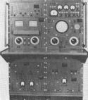
Figure 33--SP operating position. |
| INDICATOR: |
| |
Type scope |
Range scales |
| |
A |
100 miles |
| |
7" PPI |
4, 20, 50, 100, 200 miles |
| |
R |
5 miles |
| Position angle indicated on dial. Altitude in feet automatically computed, with correction for earth curvature included, and shown on meter. Correct alignment in bearing and elevation shown on moving spot scope. |

Figure 34--Approximate resolution at medium range.
--33--
MODEL SQ
| PURPOSE--Standby surface search |
| FREQUENCY BAND--S |
| ANTENNA BEAM WIDTH--: |
| |
Horizontal |
8° |
| |
Vertical |
15° |
| PULSE DURATION: 1 microsecond |
| ACCURACY: |
| |
Range, ± 200 yards on 15-mile scale; ± 1500 yards on 45-mile scale |
| |
Bearing, ± 2° |
| |
Altitude, no indication |
| INDICATOR: |
|
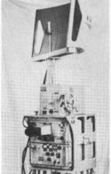
Figure 35--SQ operating position. |
| |
Type scope |
Range scales |
| |
A |
3, 15, 45 miles |
| |
B |
3, 15, 45 miles |
| |
3" PPI |
3, 15, 45 miles |
| NOTE: Choice of type a, b, or PPI presentation on single scope |
| MINIMUM RANGE: 300 yards |

Figure 36--Approximate resolution on 45-mile scale.
--34--
MODEL SR
| PURPOSE--Air search |
| FREQUENCY BAND--P |
| ANTENNA BEAM WIDTH--: |
| |
Horizontal |
20° |
| |
Vertical |
55° |
| PULSE DURATION: 1, 4, or 20 microseconds |
| ACCURACY: |
| |
Range, ± 30 yds. on 4-mi. scale; ± 100 yds. on 20 mi.; ± 2000 yds. on 80 mi.; ± 10 mi. on 400-mi. scale |
| |
Bearing, ± 2° |
| |
Altitude, ± 2000 feet with calibrated fade chart |
| INDICATOR: |
|

Figure 37--SR operating position. |
| |
Type scope |
Range scales |
| |
A |
4, 20, 80, 400 miles |
| |
1" PPI |
4, 20, 80, 200 miles |
| MINIMUM RANGE: 750 yards |

Figure 38--Approximate resolution at medium range.
--35--
MODEL SR-2
| PURPOSE--Air search |
|
INDICATOR: |
| FREQUENCY BAND--L |
|
|
Type scope |
Range scales |
| |
|
|
|
|
A |
4, 20, 80, 400 miles |
| ANTENNA BEAM WIDTH--: |
|
|
7" PPI |
4, 10, 20, 80, 200 miles |
| |
Horizontal |
8° |
|
|
R |
2000 yards from step |
| |
Vertical |
25° |
| PULSE DURATION: 1 or 4 microseconds |
|
MINIMUM RANGE: 600 yards |
| ACCURACY: |
| |
Range, ± 30 yds. on 4-mi. scale; ± 100 yds. on 20 mi.; ± 2000 yds. on 80 mi.; ± 10 mi. on 400-mi. scale |
| |
Bearing, ± 2° |
| |
Altitude, not indicated |

Figure 39--Approximate resolution with short pulse duration.
--36--
MODEL SX
| PURPOSE--General purpose search |
| FREQUENCY BAND--S |
| ANTENNA BEAM WIDTH--: |
| |
|
Search |
Height finding |
| |
Horizontal |
1.6° |
4° |
| |
Vertical |
18° |
1.2° |
| NOTE:
Antenna stabilized; height-finding beam scans 12° arc vertically.
Two separate radar systems used--one for long-range search, the other
for height finding. |
| Pulse Duration: 1 microsecond for both systems |
| ACCURACY: |
| |
Range, ± 200 yards on expanded presentations |
| |
Bearing, ± ½° |
| |
Altitude, ± ½° absolute; relative altitude may be determined more accurately |
| INDICATOR: |
|
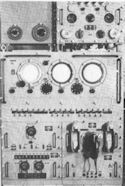
Figure 40A--SX operating console. |
| |
Type scope |
Range scales |
| |
1" PPI |
0-50; 0-100; 70-90 mi. |
| |
Off-center PPI |
10 miles |
| |
RHI |
0-55; 10 mi. expanded sweep |

Figure 40--Approximate resolution at medium range.
--37--
MODEL MK 4
| PURPOSE--AA fire control for Mk 37 director |
| FREQUENCY BAND--L |
| ANTENNA BEAM WIDTH: |
| |
|
Lobing off |
Lobing on |
| |
Horizontal |
9° |
15° |
| |
Vertical |
9° |
15° |
| NOTE:
Antenna stabilized in level and cross level. |
| PULSE DURATION: 1.5 microseconds |
| ACCURACY: |
| |
Range, ± 50 yards |
| |
Bearing, ± 4 mils |
| |
Altitude, ± 5 mils above 10° position angle |
| INDICATOR: |
|
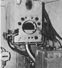
Figure 41--MK 4 range operator's position. |
| |
Type scope |
Range scale |
| |
A with notch |
100,000 yards |
| Sweep is expanded at notch. |
| Trainer and pointer scopes provided on which pips can be matched. |
| Minimum Range: 1000 yards |

Figure 42--Approximate resolution.
--38--
MODEL MK 8, MODS 0, 1, 2
| PURPOSE--Main battery fire control for Mk 34 and Mk 38
directors |
| FREQUENCY BAND--S |
| ANTENNA BEAM WIDTH: |
| |
Horizontal |
2° |
| |
Vertical |
3° |
| |
NOTE: Stabilized in level only. |
| PULSE DURATION: 0.4 microsecond |
| ACCURACY: |
| |
Range, ± 15 yards ± 0.1% of actual range |
| |
Bearing, ± 2 mils |
| |
Altitude, not indicated |
| INDICATOR: |
|
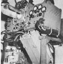
Figure 43--MK 8 mod 2 operating position. |
| |
Type scope |
Range scales |
| |
A |
20,000; 60,000 yards |
| |
B |
20,000; 60,000 yards |
| |
Precision A or B |
2500 yards |
| Type of display selected by switch--only one type available at one time. |
| B scope shows area 29° wide. |
| Minimum Range: 250 yards |

Figure 44--Approximate resolution on precision B scope.
--39--
MODEL MK 8, MODS 3, 4; MK 13, MODS 0, 2
| PURPOSE--Main battery fire control for Mk 34 or Mk 38 directors |
| FREQUENCY BAND--X |
| ANTENNA BEAM WIDTH: |
| |
|
Mk 8 mod 3, Mk 13 mod 0 |
Mk 8 mod 4, Mk 13 mod 2 |
| |
Horizontal |
0.9° |
0.75° |
| |
Vertical |
3.5° |
4° |
| |
NOTE: Stabilized in level. |
| PULSE DURATION: 0.4 microseconds |
| ACCURACY: |
| |
Range, ± 15 yards ± 0.1% of actual range |
| |
Bearing, ± 2 mils |
| |
Altitude, not indicated |
| INDICATOR: |
|
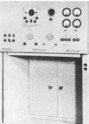
Figure 45--MK 13 operating position. |
| |
Type scope |
Range scales |
| |
A |
40,000; 80,000 yards |
| |
B |
40,000; 80,000 yards |
| |
Precision A or B |
2000-5000 yards |
| Type of display selected by switch. |
| Mk 8 mod 3 and Mk 13 mod 0 |
| B scopes show area 11° wide |
| Mk 8 mod 4 and Mk 13 mod 2 |
| B scopes show area 14° wide |
| Minimum Range: 250 yards |

Figure 46--Approximate resolution on precision B scope for MK 13 mod 0.
--40--
MODEL MK 12
| PURPOSE--AA fire control for Mk 37 director |
| FREQUENCY BAND--L |
| ANTENNA BEAM WIDTH: |
| |
|
Lobing Off |
Lobing On |
| |
Horizontal |
7°-10° |
12°-15° |
| |
Vertical |
8°-11° |
13°-16° |
| |
NOTE: Stabilized in level and cross level. |
| PULSE DURATION: 1.2 microseconds |
| ACCURACY: |
| |
Range, ± 15 yards ± 0.1% of actual range |
| |
Bearing, ± 3 mils on slow moving targets |
| |
Altitude, ± 3 mils on slow moving targets above 7° position angle |
| INDICATOR: |
|
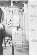
Figure 47--MK 12 range operator's position. |
| |
Type scope |
Range scale |
| |
A with notch |
50,000 yards |
| A with pip matching for bearing or elevation. |
| Moving spot for bearing or elevation. |
| Sweep may be expanded 400 yards each side of notch. |
| Minimum Range: 400 yards |

Figure 48--Approximate resolution.
--41--
MODEL MK 22
| PURPOSE--Low-angle height finding for use with Mk 4 or Mk 12 radars |
| FREQUENCY BAND--X |
| ANTENNA BEAM WIDTH: |
| |
Horizontal |
4.5° |
| |
Vertical |
1.2° |
| NOTE: Beam is scanned vertically between -7° and +6° relative to optical axis at 1 cycle per second. |
| ACCURACY: |
| |
Range, none. |
| |
Bearing, none |
| |
Altitude, ± 3 mils above 1° position angle |
| PULSE DURATION: 0.5 microsecond |
|
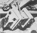
Figure 49--MK 22 indicator. |
| INDICATOR: |
| |
Special indicator used. Shows only echo in notch of radar with which Mk 22 is
used. Does not show range or bearing, but does indicate when Mk 22 beam is on in position angle. |

Figure 50--Approximate resolution. (NOTE: Although the MK 22 measures only position angle, several targets within the distances indicated will confuse position angle measurement.)
--42--
MODEL MK 28, MODS 0, 2, 3
| PURPOSE--AA
fire control |
| |
Mods 0, 3 for Mk 33 or Mk 37 director |
| |
Mod 2 for Mk 63 fire control system |
| FREQUENCY BAND--S |
| ANTENNA BEAM WIDTH: |
| |
|
Conical Scanning Off |
Conical Scanning On |
| |
Horizontal |
6.8° |
11.5° |
| |
Vertical |
6.8° |
11.5° |
| PULSE DURATION: 0.5 microsecond |
| NOTE:
Antenna elevates from -25° to +110° on mods 0 and 3, and from -15° to +85°
on mod 2. |
| ACCURACY: |
| |
Range, ± 15 yards ± 0.1% of actual range |
| |
Bearing, ± 4 mils with conical scanning on. |
| |
Altitude, ± 4 mils above 7° position angle, with conical scanning
on. |
| INDICATOR: |
|
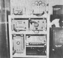
Figure 51--MK 28 operation position |
| |
Type scope |
Range scales |
| |
A |
10,000; 60,000 yards |
| |
R |
2500 yards |
| Moving spot for bearing and elevation. |
| Minimum Range: 400 yards |

Figure 52--Approximate resolution on expanded scope with conical scanning on.
--43--
MODEL MK 29
| PURPOSE--AA fire control for Mk 57 director |
| FREQUENCY BAND--X |
| ANTENNA BEAM WIDTH: |
| |
|
Conical Scanning Off |
Conical Scanning On |
| |
Horizontal |
2.5° |
5° |
| |
Vertical |
2.5° |
5° |
| |
NOTE: Antenna elevates from -15° to
+85°. |
| PULSE DURATION: 0.5 microsecond |
| ACCURACY: |
| |
Range, ± 15 yards ± 0.1% of actual range |
| |
Bearing, ± 2 mils with conical scanning on |
| |
Altitude, ± 2 mils above 3° position angle, with conical scanning
on |
| INDICATOR: |
|
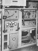
Figure 53--MK 29 operation position |
| |
Type scope |
Range scales |
| |
A |
10,000; 40,000 yards |
| |
R |
2500 yards |
| Moving spot for bearing and elevation. |

Figure 54--Approximate resolution on precision scope.
--44--
MODEL MK 34, MODS 0, 1, 2, 3, 4
| PURPOSE--AA fire control |
| nbsp; |
Mods 1, 2 for Mk 63 fire control system |
| nbsp; |
Mods 3. 4 for Mk 57 director |
| FREQUENCY BAND--X |
| ANTENNA BEAM WIDTH: |
| |
|
Conical Scanning Off |
Conical Scanning On |
| |
Horizontal |
3° |
4.5° |
| |
Vertical |
3° |
4.5° |
| NOTE: Antenna can be elevated between -15° and +85°. Stabilized in both level and cross level. |
| PULSE DURATION: 0.3 microsecond |
| INDICATOR: |
| |
Type scope |
Range scales |
| |
A |
10,000; 40,000 yards |
| |
R |
2500 yards |
| |
Moving spot for bearing and elevation. |
| Minimum Range: 300 yards |
| ACCURACY: |
| |
Range, ± 15 yards ± 0.1% of actual range |
| |
Bearing, ± 2 mils with conical scanning on. |
| |
Altitude, ± 2 mils above 4°, with conical scanning
on. |

Figure 55--Approximate resolution on precision scope.
--45--
RADAR INSTALLATIONS IN SMALL SHIPS AND AUXILIARIES

Figure 56--Destroyer (DD).

Figure 57--Destroyer escort (DE).

Figure 58--Destroyer escort (DE).
--46--
RADAR INSTALLATIONS IN SMALL SHIPS AND AUXILIARIES

Figure 59--Amphibious force flapship (AGC).

Figure 60--Combat loaded cargo ship (AKA).
--47--
RADAR INSTALLATIONS IN SMALL SHIPS AND AUXILIARIES

Figure 61--Combat loaded
transport (APA).

Figure 62--Motor torpedo
boat (MTB).
--48--
MODELS SA, SA-2
| PURPOSE--Air search |
| FREQUENCY BAND--P |
| ANTENNA BEAM WIDTH: |
| |
Horizontal |
30° (made wider by lobe switching) |
| |
Vertical |
50° |
| PULSE DURATION: 5 microseconds |
| ACCURACY: |
| |
Range, +150 yards on short range scales |
| |
Bearing, ± 1° with lobe switching on; approximately ± 4° on PPI |
| |
Altitude, ± 2000 feet with calibrated fade chart |
| INDICATOR: |
|
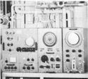
Figure 63--SA-2 operating position. |
| |
SA |
| |
Type scope |
Range scales |
| |
A |
1 5, 75, 375 miles |
| |
SA-2 |
| |
Type scope |
Range scale |
| |
A |
20, 80, 400 miles |
| |
7" PPI |
20, 80, 200 miles |
| Minimum Range: 1500 yards |

Figure 64--Approximate resolution on short range scale.
--49--
MODELS SF, SF-1
| PURPOSE--Surface search |
| FREQUENCY BAND--S |
| ANTENNA BEAM WIDTH: |
| |
Horizontal |
12° |
| |
Vertical |
12° |
| PULSE DURATION: 1 microsecond |
| ACCURACY: |
| |
Range, ± 100 yards on 16,000-yard scale; ± 300 yards on 48,000-yard scale |
| |
Bearing, ± 2° |
| |
Altitude, no indication |
| INDICATOR: |
|
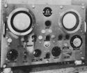
Figure 65--SF operating position. |
| |
Type scope |
Range scales |
| |
A |
0-16,000; 400-48,000 yards |
| |
5" PPI |
0-16,000; 400-48,000 yards |
| MINIMUM RANGE: 400 yards |

Figure 66--Approximate resolution on short range scale.
--50--
MODELS SL-a, SL-1
| PURPOSE--Surface search |
| FREQUENCY BAND--S |
| ANTENNA BEAM WIDTH: |
| |
Horizontal |
6° |
| |
Vertical |
12° |
| PULSE DURATION: 1.5 microseconds |
| ACCURACY: |
| |
Range, ± 100 yards on 20-mile scale |
| |
Bearing, ± 2° |
| |
Altitude, no indication |
| INDICATOR: |
|
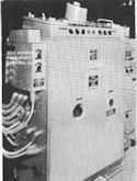
Figure 67--SL-1 operating position. |
| |
Type scope |
Range scales |
| |
7" PPI |
4, 20, 60 miles |
| MINIMUM RANGE: 400 yards |

Figure 68--Approximate resolution on 20-mile PPI scale.
--51--
MODELS SO, SO-a, SO-13
| PURPOSE--Surface search |
| FREQUENCY BAND--S |
| ANTENNA BEAM WIDTH: |
| |
Horizontal |
11° |
| |
Vertical |
11° |
| PULSE DURATION: 1 microsecond |
| ACCURACY: |
| |
Range, ± 200 yards on 20-mile scale |
| |
Bearing, ± 2° |
| |
Altitude, no indication |
| INDICATOR: |
|

Figure 69--SO operating position. |
| |
Type scope |
Range scales |
| |
5" PPI |
4, 20, 80 miles |
| MINIMUM RANGE: 200 yards |

Figure 70--Approximate resolution on 20-mile PPI scale.
--52--
MODELS SU, SU-1
| PURPOSE--Surface search |
| FREQUENCY BAND--X |
| ANTENNA BEAM WIDTH: |
| |
Horizontal |
3-8° |
| |
Vertical |
3.8° |
| PULSE DURATION: 1 microsecond |
| ACCURACY: |
| |
Range,; ± 30 yards on 4-mi. scale; ± 125 yards on 20-mi. scale; ± 500 yards on 80-mi. scale |
| |
Bearing, ± 1° |
| |
Altitude, not indicated |
| INDICATOR: |
|

Figure 71--SU operating position. |
| |
Type scope |
Range scales |
| |
A |
4, 20, 80 miles |
| |
5" PPI |
4, 20, 80 miles |
| MINIMUM RANGE: 300 yards |

Figure 72--Approximate resolution on 20-mile PPI scale.
--53--
MODEL MK 26
| PURPOSE--AA fire control for Mk 52 director |
| FREQUENCY BAND--S |
| ANTENNA BEAM WIDTH: |
| |
Horizontal |
7° |
| |
Vertical |
9° |
| |
NOTE: Antenna elevates between -30° and +115° |
| PULSE DURATION: 0.5 microsecond |
| ACCURACY: |
| |
Range, ± 150 yards |
| |
Bearing, not indicated |
| |
Altitude, not indicated |
| INDICATOR: |
|
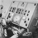
Figure 73--MK 26 operating position. |
| |
Type scope |
Range scales |
| |
J |
12,000, 30,000 yards |
| |
Measures range only. Targets are tracked optically in bearing and
elevation. |
| MINIMUM RANGE: 400 yards |

Figure 74--Approximate resolution. (NOTE: Although the MK 26
measures range only, the other resolution figures indicate the zone of confusion
possible with multiple targets.)
--54--
RADAR INSTALLATIONS IN SUBMARINES

Figure 75--Submarine (SS).
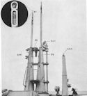
Figure 76--Close-up of submarine antennas.
--55--
MODELS SD-a, SD-2, SD-4
| PURPOSE--Air warning |
| FREQUENCY BAND--VHF |
| ANTENNA BEAM WIDTH: |
| |
Horizontal |
circular |
| |
Vertical |
circular |
| PULSE DURATION: 7-10 microseconds |
| ACCURACY: |
| |
Range, ± 1000 yards |
| |
Bearing, no indication |
| |
Altitude, no indication |
| INDICATOR: |
|

Figure 77--SD operating position. |
| |
SD-a, SD-2 |
| |
Type scope |
Range scale |
| |
A |
30 miles |
| |
SD-4 |
| |
Type scope |
Range scales |
| |
A |
15, 60 miles |
| MINIMUM RANGE: 2000 yards |

Figure 78--Approximate range resolution. Since the antenna radiates equally on all bearings, there is no bearing resolution.
--56--
MODELS SJ-a, SJ-1
| PURPOSE--Surface search |
| FREQUENCY BAND--S |
| ANTENNA BEAM WIDTH: |
| |
Horizontal |
9° (made wider by lobe switching) |
| |
Vertical |
29° |
| PULSE DURATION: ¼ microsecond |
| ACCURACY: |
| |
Range, ± 15 yards ± 0.1% of actual range |
| |
Bearing, ± ¼° with lobe switching on; approximately ± 2° from PPI |
| |
Altitude, no indication |
| INDICATOR: |
|
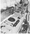
Figure 79--SJ operating position. |
| |
Type scope |
Range scales |
| |
A |
10, 30 miles |
| |
5" PPI |
4, 10, 40 miles |
| |
R |
2500 yards |
| MINIMUM RANGE: 250 yards |

Figure 80--Approximate resolution on precision scope.
--57--
MODEL SS
| PURPOSE--Surface search |
| FREQUENCY BAND--X |
| ANTENNA BEAM WIDTH |
| |
Horizontal |
2.6° |
| |
Vertical |
16° |
| (made wider by lobe switching) |
| PULSE DURATION: 0.5 microsecond |
| ACCURACY: |
| |
Range, ± 15 yards ± 0.1% of range scale |
| |
Bearing, ± ¼° with lobe switching on |
| |
Altitude, no indication |
| INDICATOR: |
| |
Type scope |
Range scales |
| |
A |
4, 10, 20, 80 miles |
| |
B |
4000 yards × 30° sector |
| |
5" PPI |
4, 10, 20, 80 miles |
| MINIMUM RANGE: 250 yards |

Figure 81--Approximate resolution on expanded B scope.
--58--
MODEL ST
| PURPOSE--Periscope surface search |
| FREQUENCY BAND--X |
| ANTENNA BEAM WIDTH: |
| |
Horizontal |
30° |
| |
Vertical |
10° |
| PULSE DURATION: 0.3 microsecond |
| ACCURACY: |
| |
Range, ± 15 yards ± 0.1% of actual range. |
| |
Bearing, optically determined. Approximately ± 5° by radar. |
| |
Altitude, not indicated. |
| INDICATOR: |
|

Figure 82--ST operating position. Selector switch for connecting SJ indicators to ST radar is encircled. |
| |
Type scope |
Range scales |
| |
A |
10, 30 miles |
| |
R |
2500 yards |
| NOTE: ST uses indicators furnished with either the SJ or SS. When it is desired to use ST, SJ is switched off and ST switched on. Set is designed for use at
periscope depth. |

Figure 83--Approximate resolution. ST cannot measure bearing accurately, but because of wide beam, two targets within approximately 20° will cause confusion.
--59--
MODEL SV
| PURPOSE--Air search |
| FREQUENCY BAND--S |
| ANTENNA BEAM WIDTH: |
| |
Horizontal |
5.5° |
| |
Vertical |
60° |
| PULSE DURATION: 1 microsecond |
| ACCURACY: |
| |
Range, ± 15 yards ± 0.1% of actual range |
| |
Bearing, ± 1° |
| |
Altitude, not indicated |
| INDICATOR: |
| |
Type scope |
Range scales |
| |
A |
10, 30 miles |
| |
5" PPI |
4, 10, 40 miles |
| MINIMUM RANGE: 400 yards |

Figure 84--Approximate resolution at medium range on A scope. Bearing resolution is approximately 5° on PPI.
--60--
Table of Contents
Previous Chapter (2) **
Next Chapter (4)


